News
Making a 12-volt portable lithium power station in less than Rs 4500


For those of you who live in your car and/or go car-camping, a portable power station is an absolute necessity.
BHPian Chhanda Das recently shared this with other enthusiasts.
DIY 12-volt Portable Lithium Power Station
We started this project on Valentine's day this year and dedicate it to our dear India on this momentous occasion of the 75th Independence Day on the 15th of August 2022.
Disclaimer
All voltages mentioned are for direct current or DC. I do not have an academic background in science and I am not very knowledgeable about electronics/electricals. My son has a background in Mathematics but he too is not very knowledgeable about this stuff. So we had to do quite a lot of research. The planning was done jointly by myself and my son while the execution of this project was largely done by my son. If you want to replicate this DIY project yourself then please do so at your own risk. And kindly bear with me since the following is a long read.
Hello everyone, this is about how we designed and made a lithium-based 12-volt power bank with a host of safety features along with the ability to deliver and accept an electrical charge to and from a wide variety of sources respectively while maintaining a scope for substantial capacity upgrades in future. We can also daisy-chain this to several other 12-volt power banks or lead-acid batteries if necessary. Basically, we wanted to make a power station along the lines of something like the ones made by brands like Jackery, Bluetti, Goal Zero, Rockpals, etc without paying exorbitant sums of money for the same.
For those of you who live in your car and/or go car-camping, a portable power station is an absolute necessity. However, some of us may not be able to access one for various reasons. For example, compact portable power stations like those made by Jackery, Bluetti, etc are usually not available here in India. The few importers who do sell them do so without any warranty support from the manufacturer. Additionally, the price at which they are listed here is usually above 200% of the price at which the manufacturer sells them due to 100% in import taxes alone. This makes such products very cost-prohibitive for us.
As some of you may know, I often go car camping in my 2017 Creta petrol 1.6 AT and I had installed a DIY solar battery charging system for the same. Although it was relatively successful, there were still a few issues that needed to be sorted.
Firstly, the charge controller that I was using was a 10 ampere rated one for lead-acid batteries which would accept very little solar power if the solar panel's voltage was lower than 13 volts. Although the 50-watt monocrystalline panel was rated for a maximum of 18 volts and was specifically designed for low light situations, the actual voltage output would often be below 13 volts in low light situations. This was because I had placed the panel on the rear parcel tray of my car and did not mount it on the roof to avoid possible legal issues or bureaucratic red tape as well as water leakage and/or rusting.
Secondly, there was little to no scope for daisy-chaining multiple batteries since I did not want to keep a lead-acid battery in the cabin of my car as those release fumes and my car's cabin also serves as my living/sleeping space. The ones that do not release fumes are quite expensive and nearly impossible to get in a desired shape/size.
Thirdly, lead acid batteries are expensive to the tune of more than INR 100 per Ampere Hour. So I had practically no choice other than to go for lithium batteries since those are way cheaper (approximately INR 18-20 per AH at 12 volts). More on this pricing aspect later. The life of lithium batteries is also higher than those of lead-acid batteries. For example, lead acid batteries like the ones used in cars have an average life of 5 years. While lithium batteries only lose around 20% of their rated capacities after 8-10 years. We still have a 5000 mAh lithium power bank from Sony that we purchased in 2012 which works fine to this day.
Fourthly, lithium batteries have very high depth of discharge (DoD) ratings compared to the 50% DoD ratings for lead acid batteries. This means that lead acid batteries can only be drained upto 50% of their rated capacities without causing permanent damage to them but lithium batteries can often be drained nearly completely and they would still run fine.
Planning and design
Lithium batteries have a host of issues mainly related to safety. As we all know, lithium batteries are especially sensitive to heat (thermal runaway) and all of us have seen/heard of explosions in phones, electric cars, electric bikes, electric scooters, tablet PCs, etc. Naturally, we wanted to avoid such situations with proper planning and extensive/meticulous testing.
Choosing the type of lithium battery
There are three main types of lithium batteries/cells available in India suitable for our particular use case - Lithium-ion (Li-ion), Lithium Iron Phosphate (LiFePO4) and Lithium Titanate (LTO) with varying ranges of voltages, charging/discharging rates and capacities. Amongst these, the LTO ones are the most expensive, longest lasting, most resistant to heat and most difficult to find while the Li-ion ones are at the total opposite ends of the spectrum. We had initially decided to go for the LiFePO4 ones since they seemed to be a good balance between price and performance but we changed our mind soon after we came to know about a dirty secret of the lithium battery business in India. Almost all of the individual lithium cells or lithium battery packs sold in India are reclaimed, refurbished and imported mainly from China even if our local sellers claim them to be brand new and this is true for Li-ion, LiFeP04 as well as LTO batteries/cells. Please note that this is not true for big brands who make electronic gadgets like laptops, phones, etc or EVs or battery packs for power stations, communication stations, etc.
We started searching for sellers across India including Kolkata where I stay but we could not find a single seller with ready shipping at reasonable rates across India. The prices they quoted for refurbished cells matched the bulk prices of new cells in China. We were naturally very dejected but still didn't lose hope. We started looking into Li-ion cells but we were appalled to see that the same situation as with LiFePO4 cells existed here as well. However, the sellers of Li-ion cells were far more in number which indicated the easy availability of these cells.
Just out of curiosity, we started looking into what refurbishing the lithium cells entails or how one refurbishes/reclaims lithium cells. Refurbishing the cells is nothing but discharging and recharging the individual cells a few times at the rated current and voltage to see if the cell holds the charge or not after a few days after the cell is disconnected from all loads and charging. If the cell retains the voltage after a few days then it is considered reusable. It is as simple as that. Li-ion cells can be easily reclaimed from dead/defective laptop battery packs and power banks. These are sold by aftermarket laptop repair shops at prices approximately between INR 60-120 with each laptop battery pack containing around 6 cells rated at approximately around 2000 mAH or 2 AH each on an average. The cells would invariably be of the 18650 size. We got a bunch of these battery packs for around INR 60 each. Please note that LiFePO4 cells are usually larger both in capacities and dimensions.
Fortunately, we had a Li-ion 4 cell 18650 charger lying around which we had procured from Aliexpress before it was banned here in India. We had procured this USB-based charger primarily to recharge the Nickel Metal Hydride (NiMH) AAA batteries for an earlier project involving DIY puddle lamps in our car but it can also recharge Li-ion 18650 batteries, LiFePO4 32650/32700 batteries and NiMH AA/AAA batteries as well. So the battery cell testing situation was sorted.
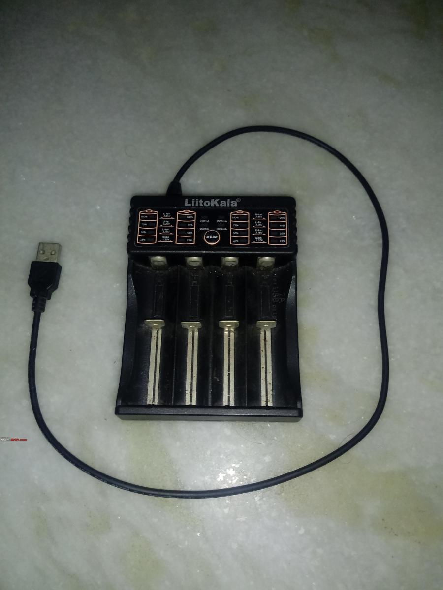
The 18650 lithium cell charger
Choosing the layout of the cells
We could not use a lead-acid battery charge controller for charging lithium cells. This is because the float voltage for lead-acid batteries is approximately around 14.2 volts while the float voltage for the 18650 model lithium battery cells (4.2 volts each) in the 3S (3 cells in series) configuration is around 12.6 volts and the same for a 4S (4 cells in series) configuration is 16.8 volts. Float voltage is the maximum safe voltage at which a minimum current can be applied to compensate for the self-discharge rate of the battery after it is fully charged. So a lead-acid charge controller can easily damage the lithium cells by overcharging the cells in 3S and undercharging the cells in a 4S configuration. Moreover, a 4S configuration meant that we would have to find a solar charge controller supporting that configuration but we could not find such a charge controller at cheap rates even after looking for 6 months. A 4S configuration also meant that we would have to use a buck converter to reduce the battery voltage for running 12v gadgets/appliances and that would push up the cost while reducing efficiency. So it had to be the 3S configuration.
Choosing the BMS
Next, we had to choose a battery management system (BMS) circuit board for the 3S configuration which should be able to handle a lot of current while having the highest safety within reasonable limits. BMS boards are necessary because lithium cells tend to get disproportionately charged/discharged over a period of time compared to similar cells in the same series. This happens with lead acid batteries (not individual cells) too especially when they are connected in series. BMS boards also have a host of safety features like overcharge protection, over-discharge protection, short circuit protection, reverse polarity protection, etc. There are two kinds of BMS boards available - active and passive. Active boards are way better in the sense that they actively monitor the voltages of each row of cells in parallel with connectivity features like App control via Bluetooth, WiFi, etc with some of them even featuring a RS232 port for LAN connections. However, these are very expensive and nearly impossible to find in India at reasonable rates, especially with the ongoing import restrictions. The only major downside of passive boards is that we have to individually balance the voltages of each lithium cell as close to each other as possible before performing the initial connections but this is easily manageable.
Tools required/used
- A small manual screwdriver kit for making the wire connections and adjusting the potentiometers on the circuit boards
- A wire cutter and stripper
- A portable 12 volt DC spot welder with an adjustable 90-130 ampere welding current
- A small 25-watt soldering iron
- A cheap multimeter to measure voltages upto 23 volts DC
- A cheap ammeter to measure direct current upto around 35 amperes with a suitably rated shunt
- A heat gun or a powerful hair dryer
- A 2 ampere USB based 4 bay lithium cell charger
- A pair of strong scissors for cutting nickel strips
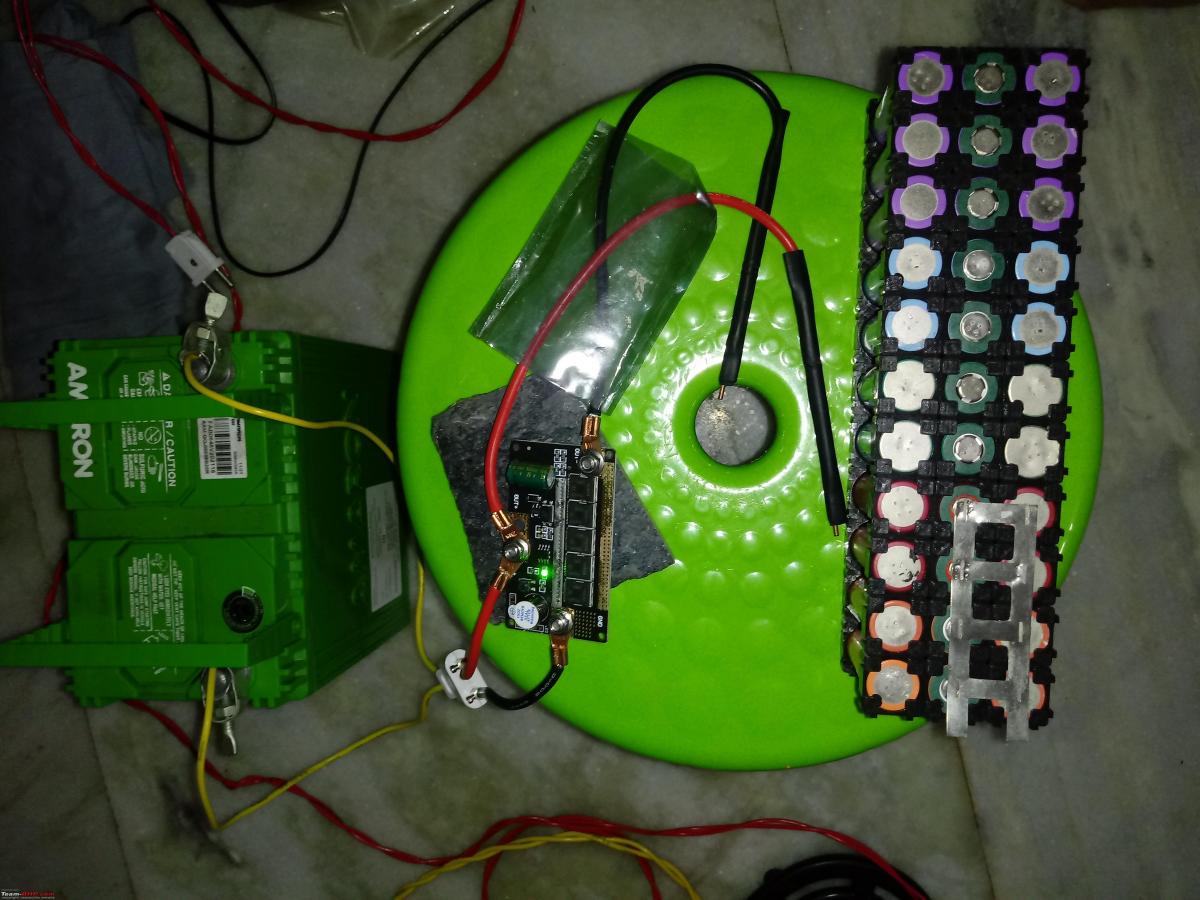
Assembling/preparing the spot welder
Please note that before using the aforementioned spot welder for the first time you will need to assemble it.
Firstly, the connectors need to be crimped onto the wires. So you will need pliers for that.
Secondly, the capacitor and the buzzer would need to be soldered onto the printed circuit board (PCB) at their respective spots while matching their respective polarities to the PCB. So you will need the soldering iron and some lead-free soldering wire for that. Here it is very important to note that if soldering the capacitor is not done properly with copious amounts of solder then this spot welder will not work as intended and will only deliver a limited amount of current.
Thirdly, you will need a battery that can deliver very high amounts of current within a short time for this spot welder. So a vehicle starting battery is perfect for this. Considering the fact that an overwhelming majority of us are vehicle owners here, arranging for a vehicle starting battery is not a problem at all.
Fourthly, you will need to install heat shrink tubes on the soldering leads for electrical insulation. Any source of flame like a candle, cigarette lighter, etc can be used for this.
Finally, you will need to screw the soldering lead wires and the wires for drawing power on the PCB (according to the colour codes and polarities) with the help of nuts. These nuts need to be tightened substantially for maintaining a proper flow of current.

The spot welder
As you can see above, the small button on the spot welder PCB beside the buzzer needs to be pressed and held multiple times to adjust the number of times (1-5) the current will be delivered upon a single contact on the welding surface. This adjustment is also indicated by aural feedback from the buzzer by the number of beeping sounds in quick succession.
Now that we have the tools sorted, let us first get into making the 3S battery pack.
Here is a list of the components used
- Square-shaped interlocking cell spacers for the 18650 model cells. These are required for passive heat dissipation during usage and holding the cells in place for spot welding. These are also available in a honeycomb shape but those are very rare. These need to be arranged in parallel in multiples of 3 for the 3S configuration. We assembled two sets containing 33 spacers in each set. These spacers cost us INR 1 each. For a larger battery pack, obviously, you will need more spacers in multiples of 6.
- High-strength plastic adhesive to help the individual cell spacers stick to each other after getting interlocked.
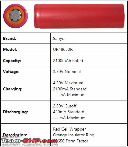
- Thirty three numbers of 18650 model cells were salvaged and refurbished by ourselves. Cost us approximately INR 12 for each 2 AH cell of 3.7 - 3.8 volts after accounting for and discarding all the defective cells. For a larger battery pack, obviously, you will need more cells in multiples of 3. Here are the specifications that we found online for most of the cells. We used 6 cells of each of the 18650 cell types whose images are provided below. The relevant images B1, B2, B3 and B4 are attached. We could not find any details online for the last 9 cells which were salvaged from a Lapcare branded battery pack and seemed to have a generic origin. These 9 cells seem to be rated at 3.7 volts each with an energy rating of 7.4 Wh (watt hour) each.
Here are the specifications that we found online for most of the cells. We used 6 cells of each of the 18650 cell types whose images are provided below.


We could not find any details online for the last 9 cells which were salvaged from a Lapcare branded battery pack and seemed to have a generic origin. These 9 cells seem to be rated at 3.7 volts each with an energy rating of 7.4 Wh (watt hour) each.
- A 3S lithium BMS (battery management system) circuit board that can handle your desired amount of current without getting hot. We chose a 40 ampere BMS and it can handle upto 20 amperes of current (charging/discharging) without getting hot and upto 40 amperes of discharging current with additional cooling. We did not need more than 15 amperes of current for our setup and hence no additional cooling was necessary. This cost us approximately INR 120.
- Thirty three numbers of single-hole electrically insulating adhesive mat for 18650 model battery cell terminal insulation. This cost us INR 1 each. For a larger battery pack, obviously, you will need more mats in multiples of 3.
- Pure nickel strip H type or 2P type with 0.15 mm thickness. You can also go for the slightly cheaper single-line strips of the same thickness as above but please avoid the nickel-plated strips. Pure nickel double line (H type or 2P type) strips cost us approximately INR 260 for 50 grams. You will need more for a larger battery pack. Also, please note that using the single line strips makes the job of spot welding them more arduous.
- Adhesive barley paper or fish paper for covering the nickel strips and terminals after making the battery pack. As an alternative, Kapton tape can also be used. Barley paper will cost you approximately INR 12 per metre and Kapton tape will cost approximately INR 20 per metre for the same width as the 3S battery pack. Another good alternative would be epoxy-fibreglass sheets if you can find them.
- PVC heat shrink sleeve of width 150 mm cost us INR 15 for one metre.
- One foot each of colour coded 2.5 square millimetre AC wires to handle upto 20 amperes of direct current (DC). Please note that you can use the more recommended DC wires but those are way thicker and will not fit the AC connectors properly.
- Lead-free solder wire
- One female 6 ampere rated 2 pin AC connector. We chose to use regular 2-pin AC connectors as our basic connectors for this entire setup instead of the more recommended DC connectors like XT30, XT60, XT90, etc. This is because the XT connectors are too tight to connect and disconnect on a regular basis and they are not widely available as well. The 2 pin 6 ampere rated AC connectors can handle quite a high amount of direct current (way more than 6 amperes) without getting hot. However, for a larger battery pack, you may have no choice other than using the XT connectors as per the load requirements. We used some red nail polish to mark the polarities on the AC connector.
- Some sand paper or emery paper
- Double-sided adhesive tape
Procedure for making the battery pack
Step 1
First, you need to rub both the positive and the negative terminals of each 18650 cell with sandpaper or emery paper to prepare them for the spot welding later. You need to be very careful not to allow dust particles to clog the vents around the positive terminals of each cell. Also, do not apply too much pressure on the cells (especially the positive terminal) or else you may damage the cells. Also, while sanding the terminals, try not to damage the PVC coverings or else you will have to rewrap the cell with the PVC again.
Step 2
You need to stick the single-hole electrically insulating adhesive mats (1 each per cell) around the positive terminal of each cell as evenly as possible without covering the actual positive terminal itself in any way.
Step 3
Then you need to arrange the cells within the spacers in such a way that the cells in the same series have the exact same rated specifications (actual voltage readings should match closely too) and the highest capacity series should be closest to the BMS. Accordingly, the battery capacities in series should be in decreasing order the farther they are from the BMS. The cell manufacturer's product datasheet should give you an idea of the cell's specifications. The cells will also need to be arranged in such a way with respect to their polarities that there is minimum usage of nickel strips. This means that in a series of 3 cells the positive terminal of the 1st cell has to be close to the negative terminal of the 2nd cell and the positive terminal of the 2nd cell has to be close to the negative terminal of the 3rd cell.
Step 4
Now place the H type or 2P type (double line) nickel strip on the battery pack in such a way as to cover the positive terminals of the row of the first cells in every series and the negative terminals of the row of the second cells in every series. It is important to note here that if the sizes of the nickel strips and the cell spacers is mismatched then you might have to cut the nickel strips and then rejoin them. Additionally, please cut the nickel strips in such a way that it sits accurately on one side of the battery pack while extending for half an inch outside the side of the battery pack on the other side lengthwise. Please note that these extensions always have to protrude on the same side of the battery pack. This is necessary so that you can connect the nickel strips to the BMS later. Also please note that if your electrical load requirement is high then you might have to use thicker nickel strips or add additional layers to the existing ones.
Step 5
Now, it is time to use the cheap spot welder. After connecting it to a fully charged vehicle battery, you need to set it to 5 or 6 beeps for it to work correctly. Please wear adequate eye protection before proceeding further. You need to spot weld the nickel strips at a minimum of 4 spots on each terminal of each cell. All you need to do is place one of the spot welding rods' tips to one of the 4 spots with a tiny amount of pressure and then do the same with the other tip of the spot welder's rod to any one of the remaining 3 spots on the same terminal of the same cell.
Repeat this procedure till all 4 spots on the terminal are connected to the nickel strip. Then do the same for the remaining cells under the same nickel strip. Please do not be afraid of a few sparks from the welding spots. At the same time, you should keep a sharp eye on the temperature of the spot welder's PCB and its wires because those will become very hot and hence you will need to allow them to cool down for at least 2 minutes after spot welding at each and every terminal of each cell. You might need to do this earlier too before all four spots of a single terminal are completely welded to prevent the spot welder from getting damaged.
Please note that during this time the spot welder may shut down to conserve energy and you will then have to restart it. However, if you use expensive/commercial spot welders then you may not have to wait at all since those usually have active cooling systems.
You need to be extra careful while spot welding the positive terminals of each cell since the working area in the middle is going to be very small and you should absolutely not try spot welding anywhere outside the positive terminal for each cell. And do not allow the welding rods to come in direct contact of each other.
And one more thing, do not apply too much pressure on the 18650 cells (especially on the positive terminals) with the spot welding rods or else you may damage the cells. And too little pressure will not help make a proper weld. The pressure has to be just right.
Step 6
Now turn the battery pack around and place the H type or 2P type nickel strip on the battery pack in such a way as to cover the positive terminals of the row of the second cells in every series and the negative terminals of the row of the third cells in every series. Everything else will be the same as Step 4 above.
Step 7
Now repeat Step 5 for the nickel strips placed during Step 6.
Spot welding in progress
Step 8
If you did not buy single-line nickel strips earlier then you will need to cut the H type or 2P type (double line) nickel strip appropriately to convert them into the single line nickel strip for this step. Turn the battery pack around and place the single-line nickel strip on the battery pack in such a way as to cover the negative terminals of the row of the first cells in every series. Everything else will be the same as Step 4 above.
Step 9
Now repeat Step 5 for the nickel strips placed during Step 8.
Step 10
Again turn the battery pack around and place the single line nickel strip on the battery pack in such a way as to cover the positive terminals of the row of the third cells in every series. Everything else will be the same as Step 4 above.
Step 11
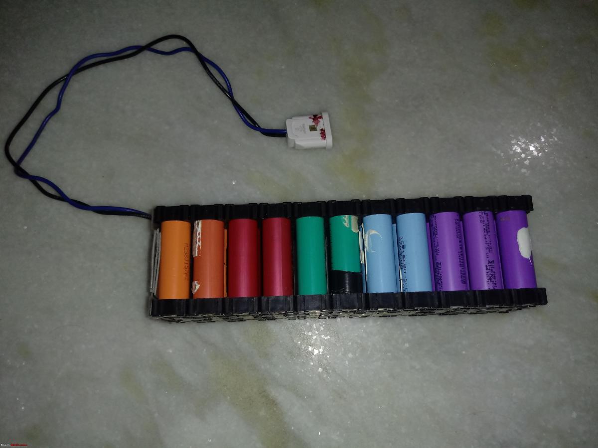
Now repeat Step 5 for the nickel strips placed during Step 10. After connecting the cells in a 3S configuration, they should look like what is shown below.

First voltage check after connecting the cells in 3S
Step 12
To prepare the BMS for the next steps, you need to apply liberal amounts of lead-free solder with a soldering iron (not spot welder) to all 6 terminals marked +, -, 0v, 4.2v, 8.4v and 12.6v on the BMS as evenly as possible. Please take special care of the terminals marked + and - while ensuring that you apply a tiny bit of extra lead-free solder. Do not short the terminals.
Step 13
Strip the insulation from the 2.5 millimetre colour-coded AC wires for approximately 1 centimetre from each side. Now connect one end of each of these colour-coded AC wires to the 2 pin AC connector's positive and negative female pins accordingly and solder the other ends of the wires to the terminals marked + and - on the BMS as per the respective polarities of the wires. Before soldering the wires to the BMS, please ensure that you have applied a generous amount of solder to the wire ends.
Step 14
Cut off the two unnecessary protrusions of the nickel strips connecting the row of the second or middle cell in every series. You should be left with 4 protrusions of the nickel strips (one for each corner) on the same side of the battery pack. Now stick some double-sided adhesive tape to the side of the battery pack that has the protruding nickel strips.
Step 15
Now stick the back of the BMS board to these adhesive tapes in such a way that the single-line nickel strip connecting the negative terminals of the first cell in every series is close to the terminal marked 0v on the BMS. As a result, the single-line nickel strip connecting the positive terminals of the third cell in every series will be close to the terminal marked 12.6v on the BMS.
Step 16
Now smoothly bend the protruding edges of the nickel strips towards their respective terminals on the BMS. Please avoid sharp bends here or else the nickel strips may break. If the nickel strip protruding edge is too big then you might have to cut it a little.
Step 17
Now you need to spot weld the nickel strips to the respective terminals in the order mentioned as follows:
- Firstly, you need to spot weld the single line nickel strip connecting the negative terminals of the first cell in every series to the terminal marked 0v on the BMS.
- Secondly, you need to spot weld the single protruding line of the H type or 2P type nickel strip connecting the positive terminal of the 1st cell in every series and the negative terminal of the 2nd cell in every series to the terminal marked 4.2v on the BMS.
- Thirdly, you need to spot weld the single protruding line of the H type or 2P type nickel strip connecting the positive terminal of the 2nd cell in every series and the negative terminal of the 3rd cell in every series to the terminal marked 8.4v on the BMS.
- Fourthly and finally, you need to spot weld the single line nickel strip connecting the positive terminals of the 3rd cell in every series to the terminal marked 12.6v on the BMS. Now your battery pack is electrically ready for use.

The BMS

First voltage check after connecting the BMS
Side view of the battery pack

Bottom view of the battery pack

Top view of the battery pack
Step 18
Now you need to stick the adhesive barley paper or fish paper on the nickel strips and the spacers on the battery pack. Then you can cover the BMS with some Kapton tape.
Step 19
Then insert the battery pack into the PVC heat-shrink sleeve completely. Just the wires and the 2 pin AC female connector should be sticking out. Now it is time to use a heat gun or a powerful hair dryer on the PVC heat-shrink sleeve. The heat should be spread evenly and should not be concentrated in a few spots or else you will damage the cells in those spots. Also, please be careful not to shrink the PVC sleeve too much or else it will start to tear.
Step 20
The battery pack is now completely ready for use and should show a voltage above 11.1 volts and below 12.6 volts. I would suggest charging the battery pack with a small direct current of around 1 ampere till the battery pack's voltage reaches 12.6 volts before using the battery pack for the first time.
Continue reading about Chhanda Das' Portable Lithium Power Station for BHPian comments, insights and more information.
- Tags:
- Indian
- Member Content
- battery
- DIY
Find Car News
Just News


.jpg)
About Us


Buy & Sell
USED CARS