News
Neatly installing reverse parking sensors on my OG Toyota Innova


I realised that driving plain vanilla cars without modern electronics isn’t cool if you are banging into trees.
BHPian shrinz.vivek recently shared this with other enthusiasts:
After years of impeccable safe driving, one fine evening I crashed into a tree while reversing my OG Innova. I was heartbroken. I had good enough reasons for the crash: I had woken up at 3.30am, had a very tiring day at work etc. But this made me realize that my mind is unable to process multiple thoughts as efficiently as it used to when I was younger. And driving plain vanilla cars without modern electronics isn’t cool if you are banging into trees.
So now I finally needed reverse parking sensors.
Immediately the “eager me” started jumping with joy sensing a DIY session. But the “lazy me” didn’t want to sweat it out and risk screwing up further. I anyways checked Amazon for a reverse parking sensor kit and was surprised to see unbranded ones for as low as 500 rupees. Then I saw some installation videos on YouTube and felt it is not impossible for a DIY but not too easy also. I told the “eager me” that I needed a calm mind and lots of time for this project which was unavailable at that moment and thus the “lazy me” won.
Off I went to KR Road and started enquiring multiple accessory shops. I was shocked to see the same product I saw on Amazon selling for more than 1500 rupees and some shops were quoting as much as 3800 bucks with installation for other branded devices like RD.
This gave some more reason for the “eager me” to persuade me to take up a DIY reverse parking sensor installation. I ordered the most reviewed product off Amazon and announced at home that Gandhi Jayanti Day is my DIY Day, and nobody should disturb me from sunrise till sunset.
I wanted to do everything as professionally as possible, as calmly as possible, as slowly as possible and end up feeling more refreshed than tired.
First, I started off by testing the whole kit at home to ensure everything works as intended. I powered up the device using a 12V power adaptor and checked if each sensor is making the display go beep beep. Unfortunately, this test made me realize how small my room is. Despite multiple attempts, I could not find an empty line of sight greater than 2.5m and hence the buzzer would not shut up. I could have shifted the whole setup into the hall and tested if the buzzer would stop, but I didn’t want to take the risk of triggering my daughter’s curiosity and surrendering the entire apparatus to her collection of toys.
Test bench

So now the stage was set for the real installation. I made a sequence of operations in my mind starting with checking the wires’ length, routing the wires, tapping the power, testing the setup and then finally drilling the holes into the bumper and fixing the sensors. Since the bumper drilling was the “point of no return” I wanted to keep it at the last so that I can abort the mission midway in case of some unexpected goofups.
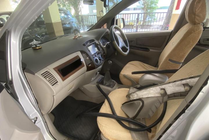
Step 1: Display installation
I decided that the LH dashboard corner is the best place to stick the display.

So, the most risk-free route for the wire to reach the rear was on the floor (under the scuff plates) along with all the other wires and rear washer hose. I saw many videos which route the wire through the beading above the door. But I decided to keep it on the floor just so that it will have the good company of other OEM wires.
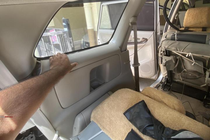
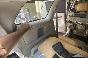
Considering the length of the power cable, the best position at which the controller could be placed was in the LH Quarter trim toolbox. So, I had to bring the display connector from the rear door into the quarter trim and out from the toolbox cover. It was impossible to pass the flimsy wire through the rear door and make it reach the toolbox. I considered passing a spring wire through the toolbox and pulling it inside like how they do for home wiring but then thought it would be an overkill. So, with a deep breath, I pulled hard and unlocked the quarter trim from the top near the quarter glass and quickly passed the wire over from the top and released the trim back. I made sure the wire was free moving inside the trim by wobbling the connector end and making sure the other end was responding with a similar wobble.
FR door area

QTR trim pulled

RR door area

Step 2: Power source
The most logical power source was the LH reverse lamp. I swiftly opened the two bolts and tried pulling the combilamp out. But it was weirdly stuck. I made sure there were no other bolts or screws holding it in place and then gave a hard pull. It came out with a mild squeak. There are two guide pins on the body side of the lamp which are made of steel, unlike plastic which is the norm. One was completely rusted and had jammed into its body hole. I made a mental note to scrape off the rust before I put it back on later.
I identified the reverse lamp wires, removed the lamp, and kept it safe.
I had not planned for professional wire taps and hence decided to repurpose a couple of spade connectors for tapping into the wires. I spliced the OEM wires with a heavy heart and twisted the skinned power wire of the controller on it and crimped everything as neatly as I could using the spade connector.
Did the same for both wires and taped everything up.
Crimped joints

Final look after taping

Now that I had my power source ready, I started testing the unit after each tiny step just to make sure nothing goes wrong after I drill holes into the bumper. Tight risk management here.
Power and display ready

Step 3: Drill the damn bumper
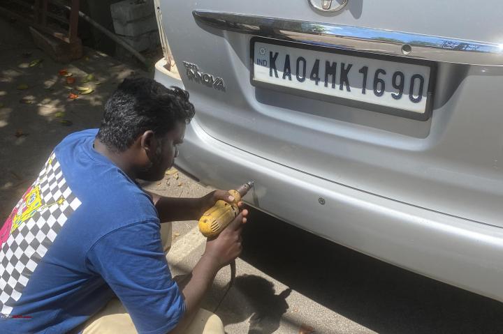
The user manual provided in the box has clear details regarding the positions of the sensors. I followed the same as accurately as possible and marked four crosshairs. I poked a small indentation to start drilling. I do not have a drilling machine of my own and usually depend on a hand drill which is older than me. Alas, all things age and my trusty old hand drill started slipping gears halfway through the first hole. After 10 mins of desperately trying to make it work, I gave up.
I put everything into the dicky and drove to a neighborhood grill welding shop. The owner is a friend of mine and has always helped me in such situations. 15 mins and 50 rupees later I had four neat holes in my car bumper. He asked me to continue working near his shop as I may need some more help later, but I chose to return to the cool shade of my covered parking.
Grill angadi guy

The cut out pieces. Gives an idea of bumper thickness

Step 4. Install the sensors
The controller has 4 ports marked A, B, C & D with A being the left most sensor and D is the right most. The same reflects in the front display unit. So, I had to install one sensor at a time, route the wire up through the gap between the bumper and the tail lamp and in through the body and out through the tool kit cover and connect it to the respective port on the connector. If I had pulled the wires of all 4 sensors and then attempted to identify which is A or B it would have been very confusing.
This was the easiest part, and I felt like all gaps and holes have been specifically designed to accommodate this accessory. I tested the whole setup after plugging in each sensor just to make sure everything is right before I patch up everything.
After multiple tests to satisfy my OCD, I did the final insertion of shoving all sensors into the holes tightly. Each sensor has 4 tiny strips of silicone-like rubber which grips the sensor in place. It was extremely irritating to make sure these rubber strips slide in and do not bulge out.
The outer ring of the sensor has an asymmetrical shape to it which is similar to a tiny beak at the top and flat at the bottom. This made me believe that the flat portion should be at the bottom and the top peak will shield the sensor from I don’t know what. But the “UP” marking on the sensor didn’t not corroborate with my theory. I went with the “UP” marking on top and chose to ignore the shape of the outer ring. If anyone has any other idea, please let me know.
Step 5: Cover everything up
I used those tiny black wire-like things which were used to tie up the wires of the kit to in turn tie the wires in place after installation too. I used it at multiple points throughout the length to keep the wires from dangling outside. I put back the tail lamp after scraping off the rust from one of the guide pins.
A lot of wires into the tail lamp hole

On the inside, I found a nice spot to place the connector on top of the metal bracket which holds the jack. But I had to route all wires from behind the jack holder bracket. I didn’t want to damage the wires or unplug anything even if I fiddled around with the jack or tools in the dark during an emergency.
Once all the wires were out of the jack’s way, I cleaned the top of the jack bracket using some alcohol-based sanitizer and stuck the controller on it using the double-sided tape provided in the box.
I finally closed the toolbox cover, and everything looked perfect!
Controller sitting pretty on the jack holder

Three hours had passed by now. My mind was happy but my body was tired. I was too hungry to take her out for a spin and test the sensors. I had tested everything a million times by now.
So thus, my DIY therapy ended. Hope many more trees are saved by this 500-rupee hack of mine.
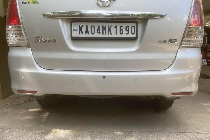
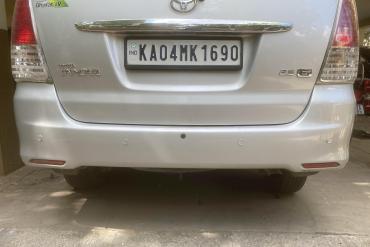
Final rear look

Note:
- This product may not be the best in quality or durability, but it’s definitely not the worst. It works as it should.
- Many of you must have noticed that my car has a reverse parking camera and yet I banged into a tree. That’s because the camera had stopped working long back and I had not bothered to replace it. I replaced it while working on the sensors with yet another Amazon find for 440 rupees. It was simple plug-and-play because I retained the existing power and video wires while replacing only the camera.
Check out BHPian comments for more insights and information.
Find Car News
Just News


About Us


Buy & Sell
USED CARS