News
DIY: Fitting an indirect TPMS on my 2016 Volkswagen Polo GT


An indirect TPMS doesn't monitor the tyre presusre. It checks the speed at which each wheel is rotating. It only warns the driver of an underinflated tyre.
BHPian prerak.kataria recently shared this with other enthusiasts.
DIY: Indirect TPMS Set Button Retrofit
For a while now I had been digging around the internet for a guide on how to install indirect TPMS on my Polo GT (2016). After failing to find it anywhere, I decided to make a guide on my own to help anyone else who is trying to replicate the same thing. My apologies if this guide becomes more pictorial, this retrofit involves a few particular elements which can't be described with words alone.
First off let's understand the difference between Direct and Indirect TPMS.
Direct TPMS
- Gives reading of tyre pressure of all the tyres at all times using sensors in the valve stem.
- Accurate tyre pressures are displayed on the MFD or Infotainment Screen.
Indirect TPMS
- Monitors rotational speed of each wheel and sends an error if any wheel is spinning faster than others, which would happen if the said wheel has lost pressure hence, reduced circumference making it spin faster.
- It only warns the driver of an underinflated tyre, without the indication of which one it could be.
- It does not monitor tyre pressure, but rather the speed at which each wheel is rotating.
Requirements for Direct and Indirect TPMS on Polo 6R
- To be able to run Direct TPMS in Polo, you need a Maxidot cluster and BCM Max before the car can accept any hardware of direct TPMS.
- To be able to run indirect TPMS in Polo, you need to have ESP and TCS Off button.
- This comes stock with automatic Polos, but some manual Polos have been retrofitted with ESP and TCS Off button as well so they can run this system too.
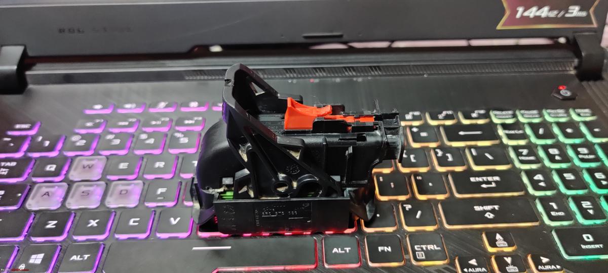
Indirect TPMS Kit
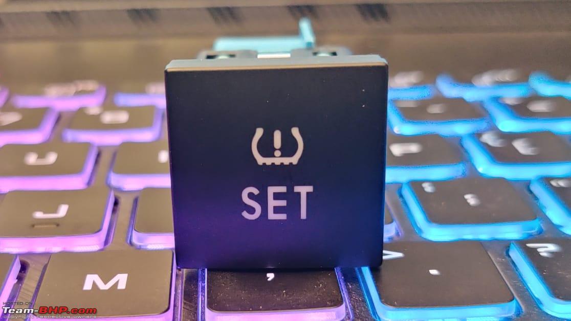
- Set Button
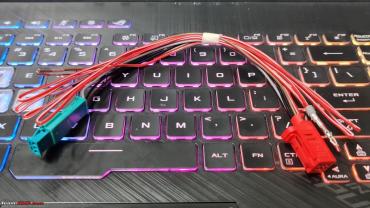
- Wiring harness

Wiring harness has a 3 pin connector in itself which accepts the pins from ‘TCS off’ button and splits the signal so it can feed power to both, ‘set’ and ‘TCS off’ buttons without tapping or splicing any wires.
And one of the wires (Red #4) runs into slot #12 of the ABS Connector.
The length of the harness is really short as it is originally for an mk5/mk6 Jetta/Golf where the buttons are in close proximity. But for this retrofit in the Polo, the ‘set’ button resides in the glove box while the ‘TCS off’ button is located above the head unit. So something has to be done for the length of this harness which we shall discuss soon.
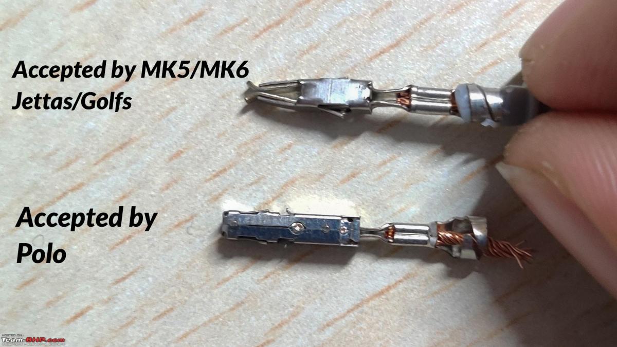
As it was originally intended to be used in mk5/mk6 Jjettas/Golfs, the pin that the ABS connector accepts has to be replaced with the correct one as well.
Wiring Options
So to wire this into your Polo you have a choice, either ignore the split of the harness and hotwire the connector of the switch or do what I did and elongate the harness to wire it as it was intended to be wired in the first place. That is by using the signal from ‘TCS off’ button.
And unless you really hate hot-wiring things in your vehicle I would recommend hot-wiring this one as reaching the ‘TCS off’ button is a headache, unfortunately.
So with an overview of the procedure, let's start from the beginning:
I extended my harness by about a meter, replaced the Pin that runs to the ABS Connector with the correct one and took the now ready harness to my car.

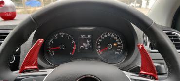
I started with breaking open the slot where the ‘set’ button was going to sit in the glove box, I was most excited about this part as everything that came next was not exactly going to be easy.

I loosened the glove box slightly to give me easy access to route the wires. I routed the harness towards the ‘TCS off’ button.
To access the connector behind the ‘TCS off’ button, you need to remove the head unit, climate control and the bracket that holds it all in place held in by 6 more screws.

2 small black arrows show the screws for climate control, these screws are slightly different as they have a blunt end, unlike all the other screws in this area which have a sharp end. (Do not mix them up with the rest).
Removing it all, you can finally pull out the ac vents and the line of buttons with them. After disconnecting the connector behind the 'TCS off' button, you need to pull out this black block that holds the crimps in place.

Using this information, you can easily route them correctly to make the ‘set’ button work properly.
'TCS Off' button black block
- 3 - illumination
- 4 - power
- 6 - ground
'set' button connector
- grey- illumination
- black- power
- brown- ground
To remove the crimps from the block, you need to push down on the tabs twice in 2 different stages while having slight tension on the wire to pull it outwards.


This is how the wires were connected in the green connector of the harness.
The wires removed from the ‘TCS off’ button were put back in as well from the harness of ‘set’ button.
- Grey (illumination) went in Slot 3 of black block (of ‘TCS off’ button)
- Black (Power) went in slot 4
- Brown(Ground) Went in Slot 6
The functioning of ‘TCS off’ was tested and it was working perfectly! Everything in the interior was put back together, Red(#4) Wire from the harness was routed behind the head unit, into the driver footwell and through the firewall through the teardrop grommet.
This red wire needs to run to slot #12 of the ABS Connector.
Opening the ABS Connector
To open the ABS Connector, you need to push the red tab on it, out of the way. Lift the black lever while slowly pulling out the connector.

To insert the crimp in place, we need to remove the plastic case on top which protects all the wires. The plastic case needs to be pushed outwards from the inside to free it from two locks on one side and lifted up.


Every connector has a purple lock holding the crimps in place, the purple lock was pushed out of the way, white rubber seal was removed with a pin, the abs connector was ready to accept the crimp.

The crimp was pushed into slot #12 and locked with the purple lock.

Mistakes Made
- I did not route the wire behind the ABS lines before insetting it in the connector (I later had to introduce a cut in it to route it properly).
- I forgot to lock the crimps with purple lock at first, unless you lock it, the ABS connector won’t go in, I was stuck here clueless for solid 5 minutes before realising my very dumb mistake.
- I did not disconnect the battery(just removed the key from ignition) and I was greeted with abs errors during my first scan after this retrofit. Please disconnect the battery while performing this retrofit.
Be careful of
While trying to put the abs connector back in, you might need to use a lot of force to pull the tab to lock it in place, for leverage on your palm you would instinctively want to use something and there are abs lines nearby, stay away from those as they’re fragile and ruining one line would not just be fatal but very expensive as well.
VCDS Coding
With the hard part taken care of, now comes coding.
- 17-Instruments> Coding> long coding Helper >
- There will be a bit reading 'Tpms active/installed', tick that on.
Then in 03-ABS Brakes
- 07-coding>long coding > L.code2>
- Last Byte (17) Activate Bit 0
These are the two modules you need to code, after coding it, kill the ignition, give it ignition again and you should notice the TPMS light in your cluster stay on with the rest of the warning lights and vanish as well.

- Clicking the 'set' button should make the TPMS light glow up in the cluster.
- Long Pressing the SET button would reset the values and there will be an audible confirmation to confirm that the values have been reset.
At this point, let the ABS learn. Drive for 50 or so KMs (More if possible) before testing it. I drove for one full day after resetting the values and came back the next day to deflate one tyre. I chose to deflate a rear tyre, as those go unnoticed easily, front tyres give a lot of signals and feedback when they're low in pressure.

I must have deflated it down to 15 PSI, that is a major difference but looking at the tyre one can easily miss the flat spot and drive away without raising any alarms.

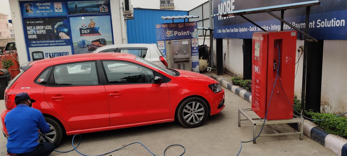
The nearest petrol pump is less than 1 km from my house, I took the longer route to get there, hoping the TPMS light would come up.
Within the first 800m, the amber glow of TPMS light popped up with an audible chime, I have never been happier hearing that sound and seeing an amber glow shine in front of my eyes.
I was very happy with how quickly it caught the difference in circumference, but that could be due to the high-pressure drop, I had introduced a huge pressure drop and it was easier for the system to recognise a difference in circumference.

Happy with the system's functioning, I was ready to get rid of this error from my dash. I headed to the petrol pump right then, waited in the queue to get nitrogen-filled back in my tyres.
Just getting the air-filled won't make the error vanish, however, for this very reason we did the hard work of installing the 'set' button.

Long press the set button to command the ABS to reset the values and start learning the circumference again.

You will have an error-free cluster and an Indirect TPMS working for you, monitoring your tyres for you at all times!
This was my first time working with ABS Connector, I have had experience with working on cars for a while now, but this retrofit is something I would not recommend a newbie to perform.
ABS and its functionality are highly crucial and mistakes made can be expensive. That said, this should not be very difficult for a daily wrencher or an FNG to perform. (Perform it at your own risk).
I had been looking for technical information on this retrofit after I got hold of this kit, so I could install it in my car, I could not find much information for my Polo 6R, maybe because it is not a very common or exciting retrofit.
I am hoping this guide will be useful to anyone who wishes to replicate this and I hope the readers learnt something new from this guide.
Check out BHPian comments for more insights and information.
- Tags:
- Indian
- Member Content
- Volkswagen
- Polo
- DIY
Find Car News
Just News


About Us


Buy & Sell
USED CARS