News
Converting my Alto's stock ORVMs into electrically adjustable ones
I chose the Hyundai i20's actuators because the dimensions looked quite promising for my Maruti Alto's mirror dome.
Hey Everyone,
I was having an urge to control my left mirror while sitting at comfort on my right seat, but Alto didn't have one. So I took this way to convert my existing Internally Adjustable Manual ORVMS to electrically actuated ones.
Materials:
- Internally/Dome-feather touch type Adjustable ORVM (Ignore if you already have them). For BS-2 to BS-3/4 till 2011 Alto Owners, check first gen alto K10 mirrors
- I20 Actuators (LHS and RHS)
- Mirror adjustment joystick (Maruti Suzuki)
- 18/20 AWG wires
- Couplers with pins
Tools/Consumables:
- Hot Glue gun
- Soldering Gun
- Hot air Gun
- 12V supply
- Crimping tool
Personally, most of my tools are from Ingco since they are cordless and all share the same battery.
Some Questions before we proceed:
Why I chose i20 actuators?
The dimensions looked quite promising for Alto's mirror dome, though I was not sure about mounting, earlier I had thought that I would 3D print an adapter to fit the actuator to mounting points inside the mirror cover. But that was not required as two screw points just mount easily.
Why use Maruti's switch?
Again, no such particular requirements, except that I found it cheaper than others, and Boodmo's free delivery sale.
Do you need to buy any additional auxiliaries for this project?
No, but I did buy a fuse box and silicon wires since they are flexible and better. So this is completely based on one's preference.
What are the risk factors/wastage and precautions?
Mirrors are extremely fragile and you might have to be careful while pulling them out of their brackets. You might also have to delete the frame that holds the mirror.
Other than that, if you are using Internally adjustable ORVMs, you have to remove cable adjusted setup, which might be irreversible in case you would like to abandon the project, so proceed with dexterity and patience. Since we have no wiring harness (or would really need one) and their couplers, insert the pins carefully in actuators and switch so as not to short one another. Check with multimeter if all pins are seated correctly without shorts then proceed to fill in the glue.
Hazard of electric shock while working with a 12V bench supply, ensure you have proper ground, and your bench supply has all safety facilities.
Glue from a hot gun nozzle can be very hot, ensure not to touch the hot nozzle or take care of hot glue not dropping/touching your skin.
Let's get into the project now.
Preparations:
The Mirror Joystick switch:
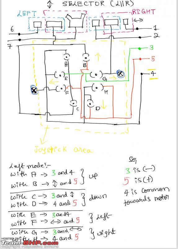
Start with figuring out the pins of the switch if you are using any other switch than mine. You can use continuity check on your multimeter which tells you what pin leads to what circuit behind certain buttons. Then you need to devise the logic based on that behaviour. Here is what mine looks like:
Actuators:
Once you are done with the switch, attach wires (I assume you might not have or need a wiring harness that has an appropriate coupler), time for adding wires to the actuator(s) you bought for mirrors.
I have added wires by individually connecting each pin with the female pin we normally use, and added hot glue on top like this for both actuators and switch:

And this is how the mirror switch looks like:

Test the wires as per pin (for i20 specifically/or in retrospective applicable to 3 PIN actuators). Pin arrangement looks something like this:

Connect actuator wires to the switch, hook up power supply and start testing how the actuator moves. You might get confused easily so ensure you are looking at the actuator in the correct angle so that up-down left-right motors are aligned correctly. Here is a demo on identifying how to orient.
Once you are done with the above prep and testing, time to move to the car.
Fixing actuators inside car mirrors:
Couple of points to keep in mind:
Though your suggestions are most welcome, here my approach is a little destructive towards some mirror parts and is mostly irreversible so please plan accordingly.
Remove the mirrors from the car: To avoid scratches on the mirror's outer shell (especially if it is painted), set your workbench accordingly by using soft foam/cloth to protect the finish.
Start by grabbing the mirror holder out of the adapter.
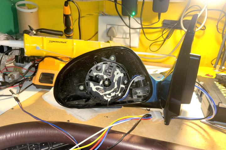
Once the mirror is out, remove all components from inside which include 3 mechanical cables that run towards the knob (if internally adjustable ORVM). Be careful not to put excess pressure on the mirror while trying to pry it up from its holder. These parts are now removed from the mirror:

You might also need to shave off some extra plastic parts that protrude out hindering the movement of the actuator with the soldering gun.
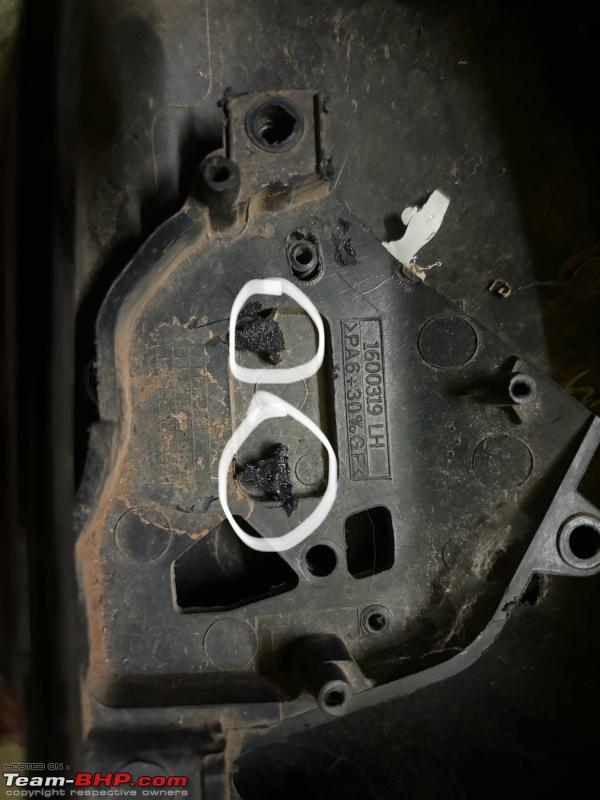
Make sure to align the actuator and fit the actuator inside ORVM seated on two screw mount points. Note that you will only be able to use only two screw mountings as the third one falls outside and should be left.
Pass the wires through the cylinder that holds the dome cover, and run them inside just the same way as mechanical cables.

Assuming you have checked and see that the actuator turns its face corresponding to Joystick buttons, you will now need to attach a mirror on the actuator.
Remove the plastic adapter that is wrapped around the mirror glass, carefully cutting small bits on its border while ensuring not to penetrate deep into the mirror.
Once taken out, clean the glass and actuator surface perhaps with alcohol.
I suggest you to stick some tape behind the mirror that is outside of the mating surface area on which the actuator should be struck. Reason is in the event of a collision the mirror should not shatter and debris fly towards people's faces.
Then apply Glue covering mostly central parts on the actuator, wait for 1 min and just let the mirror sit on the glued surface. If you want to make corrections possibly within the first 5 mins.

Leave it at least overnight before returning "ears" back to the car.
Once the mirror is attached properly, just add the coupler to those 3 wires. This should be done at last because once you add couplers, it might be difficult to remove them again in case something goes wrong.
Wiring:
I usually build complete wiring harnesses because that can be more maintenance-friendly requiring no cutting wires in case you have to take them out.

You can hook up the power wire (+) to accessories or ignition (personally I would do it to ignition) with a fuse in between for added safety.
This is how mine looks like:

This is the LH and RH door harness that I custom-built, including power mirrors, power windows and a central lock actuator together.
The Mirror wiring harness inside the dashboard:

Side DIY in case you are unable to source any one of the actuators, as mine. I was unable to get the Right side actuator for the i20 so I modified the left to work as a right actuator by swapping one of the motor's polarity:

Working (YouTube Demo)
Check out BHPian comments for more insights and information.
Find Car News
Just News


About Us