News
Tech Travelogue of the 115-year old Nilgiri Steam Mountain Railway
.png)
The 'Nilgiri Railway Company' was registered on September 30, 1885 with a nominal capital of Rs.2.5 million.
BHPian vivee90 recently shared this with other enthusiasts.
Hello folks,
Almost a year after my last thread in tbhp, I am happy to write down my experience of the Nilgiri Mountain train from the perspective of an Engineer.
And here she is, all set for chugging through memories of another million travelers

Intro to the trip
I am from Tamilnadu and Mettupalayam is my parent's hometown. Many times, during summer vacations I have heard the steam engine whistling on its way to the Nilgiris in the distance. Having always wanted to experience it, life stood in-between for almost 3 decades. This year, I created an opportunity in the mask of taking my three and half-year-old son on a day trip. Incidentally, we happen to travel on the day before the 125th anniversary of Nilgiri Mountain Railway (June 15) making it extra special.
The only intention of the trip was to experience the steam train and not sight-seeing. So, I booked up and down tickets on the same day for the Mettupalayam to Coonoor stretch. This is the steam engine stretch and upwards from Coonoor to Ooty, the diesel engine takes over.
And what I mean by experience is not just as a traveler from platform to platform but more like a 'behind the scenes tour', looking at how the loco is prepared, how it is shunted to the coaches, the maintenance, and the kind of backstories from mechanics than entice an Engineer.
As much as the journey, the couple of hours we spent in the Coonoor maintenance yard exploring and talking to the mechanics about the whereabouts of the steam loco were fulfilling. So, you know what to expect!
Intro to the Railway Line
I read that the British wanted a respite from the hot weather and developed the hill station as a retreat. And soon, it also became significant for the military which added to the purpose of building a reliable transport means. The 'Nilgiri Railway Company' was registered on September 30, 1885, with a nominal capital of Rs.2.5 million. The first stretch of line from Mettupalayam to Coonoor was constructed between 1886 and 1899 and opened for traffic on June 15, 1899. It boasts the steepest gradient of 1:12 (8% gradability) among all tracks of Indian Railways.
The initial route that ran up to Coonoor was later extended to Fern Hill and to Ooty in the 1900’s.
The track is metre gauge (0.6 meters) and spans 46 kilometers between Ooty and Mettupalayam. A remarkable aspect of the track is that it ascends from an altitude of 1069 Feet to 7228 feet, an impressive 6000+ feet within just 45 kilometres, making it the steepest rail route in Asia and second in the world (source: NMR Brakeman's handbook)
What makes it special? The Alternating Biting Teeth (ABT) system
The unique aspect of this railway line is not just the steam locomotives but also what sits in between the two rails of the track.
ABT is a Rack and Pinion arrangement to climb the steep gradient. Between the two rails is a pair of two closely placed racks. Racks in engineering parlance is linear gears. The teeth on the two racks are not in sync, but out of step with each other. To provide a simple analogy, this acts like a ladder for the train to climb up the steep sections.


The hands and legs that work up on this ladder are the 2 gears (a.k.a Pinions / Cogs) on the underside of the train. Another unique aspect here is when I mention "the train", it is not just the loco (popularly referred to as Train Engine) but also each wagon (a.k.a rake or coach). Each coach has a pair of cogs that are independent of the loco propulsion. They engage themselves on the teeth on the rack and use them as the steps of a ladder, thus preventing any slip on the steep sections. These are controlled by levers on the coaches by the brakesman.
The cogs are present in the leading axle of each coach.

Note that only the cogs in the engine are driven by steam power, the ones in the coach are engaged to provide traction to prevent slip. They are basically free wheels with only braking.
The racks start to appear amidst the track from Kallar station, which is 20 mins from Mettupalayam. 200m after the train leaves Kallar, the stride gets into full steam as the train’s pinions grab onto the racks to climb the steep ascent. The engagement is a noisy affair, and any one with decent observation can point out when the Pinions engage due to the grinding noise and the sudden lurches.
Some numbers are taken from the info plates in the museum,
- Total Distance: 46 Kms.
- Duration Up: 4 hours 45 minutes
- Duration down: 3 hours 30 minutes
- Number of Stations: 10
- Number of Tunnels: 16
- Rack & Pinion (ABT) System: 19.5 Km
- Number of Curves: 209
- Bridges: Large 28, small 98
Gradient Profile,
- 1 in 40 on the section between Mettupalayam to Kallar,
- 1 in 12.28 from Kallar to Coonoor (Rack system)
- 1 in 23 from Coonoor to Udagamandalam.
t is incomprehensible to my mind how they planned this in the first place. Credit where due to conceiving this marvel. What must have begun as summer transportation for the Brits, evolved into a strategic asset, and now over time, it has become a legend in itself!
Story of the Locomotives
The working of Steam Engine
Fuel (Coal, Furnace oil, Diesel, and whatnot!) is used to heat up water in the boiler and once steam is generated, it is manipulated through valves to push the piston. The piston directly drives the wheel through a series of connecting rods and a link mechanism.
The ability of the valves to manipulate the steam pressure to the piston means that the Torque to drive the wheels can be controlled. When no power is needed, there is a pressure relief valve at the top of the boiler that will release excess steam outside to maintain threshold pressure. It's a safety device that maintains steam pressure in the boiler within the threshold. So, you can see steam bellowing from time to time from the top when the locomotive is at rest
While the locomotive is producing steam, the amount of water in the boiler is constantly monitored by looking at the water level in a transparent tube, or sight glass. Efficient and safe operation of the boiler requires keeping the level correctly. If the water level is too high, steam production falls, efficiency is lost and water is carried out with the steam into the cylinders, possibly causing mechanical damage. The fireman is responsible for that. He shares the cab duty with the Pilot who manages the locomotion part.
Start-up on a large engine may take hours of preliminary heating of the boiler water before sufficient steam is available. In the case of NMR locos, it takes about an hour thanks to some modern adaptations.
The Drive train
The cylinders are double-acting, with steam admitted to each side of the piston in turn. In a two-cylinder locomotive, one cylinder is located on each side of the vehicle. The cranks are set 90° out of phase.
During a full rotation of the driving wheel, steam provides four power strokes; each cylinder receives two injections of steam per revolution. The first stroke is to the front of the piston and the second stroke is to the rear of the piston; hence two working strokes.
Consequently, two deliveries of steam onto each piston face in the two cylinders generate a full revolution of the driving wheel. So, the full 360-degree rotation of the wheel is powered.
Each piston is attached to the driving axle on each side by a connecting rod, and the driving wheels are connected together by coupling rods to transmit power from the main driver to the other wheels.
The arrangement,

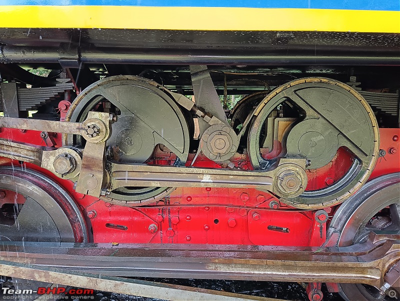
The NMR locos are compound locomotives with four cylinders. The two high-pressure cylinders at the bottom on either side are used for the adhesion system and two low-pressure cylinders, positioned above the two main cylinders are used to drive the cogs. The railway parlance for the main drive train powering the wheels is the "Adhesion system".

On the easier section of the line, with no rack rail, the locomotives work as two-cylinder simple expansion engines. So, the locomotive can function in 2 modes, the first "compound mode" where the steam powers all 4 cylinders, and the "stage mode" where the wheels or cogs can be independently powered. The tractive effort split is 57:43 adhesion to rack drive in the "compound mode". The low-pressure cylinders turned the two rack wheels via a 1 to 2,1 reduction gear. The position of these rack wheels can be seen between the second and third driving axles.
I am not sure why they would want to independently run only the cogs. Maybe it's only for testing. I saw in a video (link attached in next post) that the cog system was running when the engine was idle.
Quite a system like the 4WD and the AWD in the road vehicles!
Once the steam has done its primary job of displacing the piston, then it is directed to the chimney along with the exhaust from the fuel. In the case of NMR though, the steam does additional duty as well. After it does its job of pushing the main piston, sometimes it is diverted to the secondary piston for the ABT system to power the cogs in the locomotive.
But I noticed steam being released at the bottom many times in the stations. I later learned that steam is also used to clear the cylinder of any residual water that might have condensed inside. It is a critical safety step as any condensed water might lead to piston blow-up as water is not compressible.
The NMR Loco
Some history to begin with,
The locomotives were originally made by a Swiss company (Schweizerische Locomotive and Maschinenfabrik, Winterthur) and are called X-class locos in 0-8-2RT configuration. It is said that the very first British-made locomotives couldn't perform as expected and the Swiss company proved their mettle!
These engines were purchased in two lots. The first batch of twelve was delivered between 1914 and 1925, and the second batch of five was delivered in 1952. Four more members of the class were built in India between 2011 and 2014, and another two between 2021 and 2022 in Trichy. These engines are homed at the Coonoor shed of Southern Railway with periodic overhauls done at Golden Rock Railway works, Trichy.
Specsheet
- Size 9990m length, 2490 m wide and 3430m height.
- Tare weight 50.3 T
- Power 900 hp
- Hauling capacity - Approx 97 T
- Torque 12179 kg.
- Maximum speed
- Without Rack: 30 kmph
- Rack engaged: 15 kmph
- NMR Specific speed limit,
- 22.5 kmph speed up for MTP to ONR,
- 11.8 kmph both up and down when ABT is engage
(Source: NMR Brakesman Handbook)
The Construction of Class X
The locomotive is built like a ladder frame construction, where the boiler, and crew cab are attached to the top over a leaf spring suspension. There are approximately 3461 components (253 sub-assemblies) in the loco including the motion and brake systems. All elements are mounted on the rigid frame using various fastening methods.

So, this class of locos has a 5-adhesion wheel assembly. The main connecting link from the piston drives the main axle which then links to other axles to propel the loco. In this case, 3 other axles take power from one main driven axle.
The layout of the critical parts,

While trying to understand the wheel notation in the Engine specs, I came across an interesting classification.
The Whyte notation is a classification method for locomotives wheel arrangement. The order is "Leading wheels - Powered wheels - Trailing wheels" The NMR locos have the classification of 0-8-2RT, meaning 0 leading wheels, 8 powered wheels, and 2 trailing wheels. The RT stands for Rack system. I read that in order to allow for more flexibility in curves, the first and fourth driving axles were movable sideways. Not sure, if this still works that way.

I couldn't help but relate it to the current truck industry where axle notations are used to denote the powered and free axle configuration.
Energy source
Till I first saw the crew cab of the loco on the day of the journey, I believed that the boiler was coal-fed. It was a surprise to see a Spanky cab with no traces of coal litter. Hiding my embarrassment,I went on to strike up a conversation with the loco pilot who was sitting on the platform with his earphones on. For a moment, I felt like seeing an F1 driver sitting on the sides of the starting grid preparing for the race.
Now back to the facts,
In 2002 the coal was replaced with an oil-fired system and then later to High-speed Diesel. I read that about 4 tons of coal was required for each trip and it was all manually shoveled inside the fire room! I can think of multiple reasons for this evolution and am sure you too will.
The coal? what coal? moment, the interior of the crew cab controls
Photo of old coal litter from the retired engine vs the current one,

Another advantage of the fuel transition is the reduced crew requirement. Coal-fired systems require two firemen, but now only one fireman needs to travel with the driver. It doesn't stop there, furnace oil is now replaced with high-speed diesel, as it is less viscous and contains less sulfur. Thus, mitigating some environmental damage. The conversions were carried out in Golden Rock Workshop in Trichy in the past decade.
Furnace Oil Spec from the museum

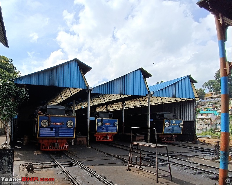
Periodic Overhaul (POH) of the steam locomotives is done at Golden Rock Railway Workshop in Trichy.

Daily maintenance is done at the Coonoor loco shed. Functioning since 1899, the place is a legend in itself! A must-visit place for enthusiasts. It is not technically open to the public, but the staff are kind enough to let us explore.
Made in India variants
Thanks to a nice video from the Golden Rock workshop about reverse engineering the Locos, many aspects of the train that I mentioned are from this reference. Fun fact is the original locos were designed in metric dimensions unlike the British system thanks to the Swiss origin. So considerable time was saved in not having to convert all dimensions in the original drawings. It must have been an exciting project and am sure the hard work is worth it.
Sometime in 2000, the railway workshop started work to make 4 more of these locos. The first one (No. X 37396), named Neela Kurinji, arrived in February 2011 and entered service on March 24 of that year. The second (No. X 37397), Betta Queen, was rolled out at the Golden Rock Railway Workshop in February 2012 and entered service on the railway in March. The third (No. X 37398), also from the Golden Rock Workshop, Nilgiri Queen, entered service in March 2013. The fourth (No. X 37399), named Nilgiri Flycatcher was rolled out on March 5, 2014.
Made in India Neela Kurinji, is named after the wildflowers in the hills ready for the day's duty. She had an uphill task (literally!) and she managed it with grace on our date.

The odd mod job
The steam locos have been retrofitted with on-board generators for powering the burners, blowers, water pumps, oil pumps, and auxiliary electrical power. The odd exhaust piping you see jetting out from the cabin area is the aesthetic price for this utility.
Braking system
There are 4 braking systems in the train. Vacuum braking, dynamic braking, hand brake, and band brake.
As much as the boiler provides the steam power to move, it also plays a role in providing braking effort. This system is called vacuum braking and is actuated by a large master cylinder mounted on the side. This effort is transmitted by vacuum hoses connected to all coaches from the engine. So apart from the mechanical coupling, there is also a vacuum coupling between the wagons.
I also heard about Steam compression braking from one of the mechanics, but not sure about it. I would assume it to be something similar to engine braking, but steam is let in the cylinder to reduce speed. Would love to know more about it.
The third is the braking system that is similar to the hand brakes. Mainly used to prevent accidental rolling of the adhesion system.
The fourth braking is for the cogs, it's a simple belt-based friction brake used when in rest.
Image of such hand brake implemented in the cog system, the belt loop makes the pattern of infinity. Once the pilot activates the lever, the central pivot rotates to tighten the loop over the wheels.
In one of the manuals, I also learned a new term called "Sprag brake" which was familiar by the method but not the name.
Photo of wedge brake applied in one of the water stops along the way.

Braking in the Coaches
Another unique aspect of this train is that the coaches have their own control mechanism for engaging the rack and pinion system. From what I gathered, the red and yellow levers are used for engaging the gears in the track and for applying brakes.
The Pinion is provided on the leading axle. So, there is a coach manager who doubles up as a ticket checker and brakesman. He/She ensures the mechanism is aptly set up in the steep sections and during stops.
Image of levers at the back of the coaches (Source: team-bhp

It is not clear to me how the cogs are engaged (lowered and raised) to the rack. But am sure, it is done individually for each coach by the brakeman.
The coaches are also equipped with Vacuum brake (from Loco) apart from the hand brake for the pinions.
Coach build
The coaches we got to travel were coaches introduced in 1931 and rebuilt in 2005 at GOC. Lesser said than better about the coach's interior and build. At least the regular ones we got to travel, to is all Jugaad work. Nothing heritage nor engineering about it.
Coach specs,
- Approx 10.3m, 2026m wide and 3.16 height
- Tare weight 13 to 16 Ton

I did see some shiny new coaches in the yard though! I later found out that those were made by ICF in 2019 but it's a pity, we didn't get to ride in that. I could only see with envy as the coaches were connected to form the next day's train. Maybe they use it only on the anniversary days!
A mechanic mentioned that the coaches undergo inspection and maintenance after every run at Mettupalayam and they have enough coaches to swap them daily. So, the locos are serviced at Coonoor and the coaches at Mettupalayam.
Water consumption
Approximately 500 liter per km is consumed when chugging up the hill. There are 3 water stops along the route to fill up. That way, there is no need to transport water in a separate wagon. So much for the steam power
Some more images,

The SS tanks have a capacity of 4500L and are fitted on the either side of the boiler. This kind of mounting is called Pannier type construction. Pannier tanks are box-shaped tanks carried on the sides of the boiler, not carried on the locomotive's running plates. This leaves a space between the tanks and the running plate. Pannier tanks have a lower center of gravity than a saddle tank which sits on the top of the boiler. In this case, we have the diesel tank in the saddle position.
An interesting engineering connection I could make with the water tank-boiler design is the ability to supply water to the boiler and maintain pressure inside the boiler in the steep slopes. Similar consideration is given in modern-day automobiles when designing fuel tanks for SUVs (actual ones that offroad!) and Engine oil pans for race cars. An engineering connection from steam engines to Nascar engines, ensuring a constant supply of fluids when inclined!
Lubrication
And the stops are also critical to lubricating the joints and bushes. I learned that there aren't many ball bearings, and it is mostly brass bushings that take up the job of reducing friction. And lubrication system is old-school mechanical as well, meaning one has to top up every while to make sure the sliding joints and couplings work smoothly. There were multiple reservoirs mounted near the linkages that led to a drip-type lubrication. It's topped up at each stop by a dedicated person.
Video of lubrication oil dripping
Apart from this, there is also a hydrostatic lubrication system in the cabin for the rack and adhesion cylinders.
Fuel consumption
The diesel tank that sits on top of the boiler has a capacity of 1600L and another tank for the generator at 750L. (Source: unofficial southern railway fb page). A mechanic told me it serves good for a day's trip, that is up and down plus shunting duty. This information needs verification. The diesel tank integration is very gracefully done, unlike the aux generator.
The large black dome you see on top of the boiler is the diesel tank.
Image of the new loco with diesel and the original heritage one,
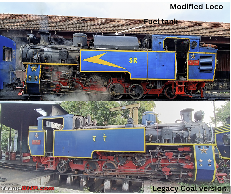
Note: The loco in the bottom part is one of the original ones brought from Switzerland.
To pull or push?
The Loco is always coupled to the coaches on the downhill side and in the same orientation where the boiler is facing the coaches. Unlike what is popularly mentioned about the orientation of the loco changing when ascending and descending, I found that the loco was attached in the same orientation both ways.
When I asked the loco pilot about it, he said it was mainly to get a good view of the track and there is no technical reason per se. I also realize that the Engine's power output is the same for both directions, unlike an automobile's powertrain. This is a unique advantage of not having a conventional gearbox-based ICE powertrain where we will need 2x the gears.
In that way, the steam system with linkages is similar to Electric motors. An interesting insight into powertrain architecture! As a matter of fact, even the Diesel locos have the same advantage due to the electric traction motors that drive the axles.
Check out BHPian comments for more insights and information.
Find Car News
Just News


About Us