| |||||||

| Search Forums |
| Advanced Search |
| Go to Page... |
 |
| Search this Thread |  80,211 views |
 9th June 2023, 18:03
| #1 |
| Distinguished - BHPian  | Anatomy of a Car AC Compressor (clutch/variable) We have some excellent threads on the forum about airconditioning, notably car AC systems, obviously!  I have worked on the AC systems of my Jeep Cherokee and my wife Ford Fiesta during the last 12 months or so. All detailled in my thread of fiddling with my cars. At the end of this post I will provide links to each repair job. Recently my friendly AC specialist and neighbour Jack and I replaced the AC compressor on the Fiesta. I thought it would be interesting to open it up and get a feel for what is inside. According to my mum I started taking things apart from when I was about 3 years old. Initially, I did have problems putting stuff back together again. Apparently I took our central heating furnace apart when my parents were not looking. They only noticed when it was getting cold in the sitting room, and they had to call in a specialist to put it back together again. These days I do manage a bit better. Usually I manage to put things back together. I also wanted to take this compressor apart to see if, over time, I can make it into one of these ‘cut-away’ display thingies. Would look pretty cool in my garage!! So buckle up and lets rip this compressor apart!! It is going to get a bit technical, if not nerdy. Mostly all mechanical so I hope most folks can follow! 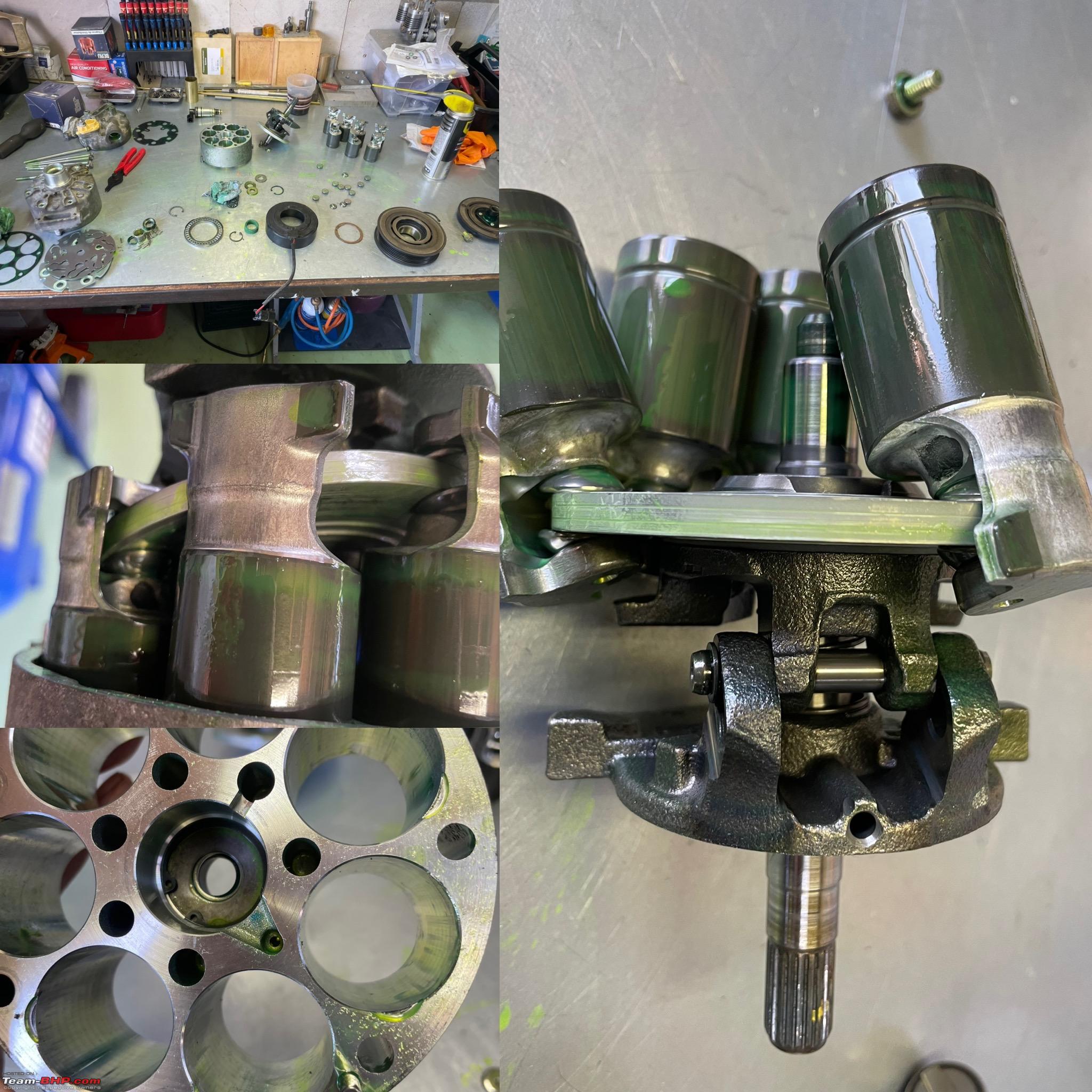 I am not going to explain in detail how an AC system works. Just a brief very general explanation. Have a look at this diagram 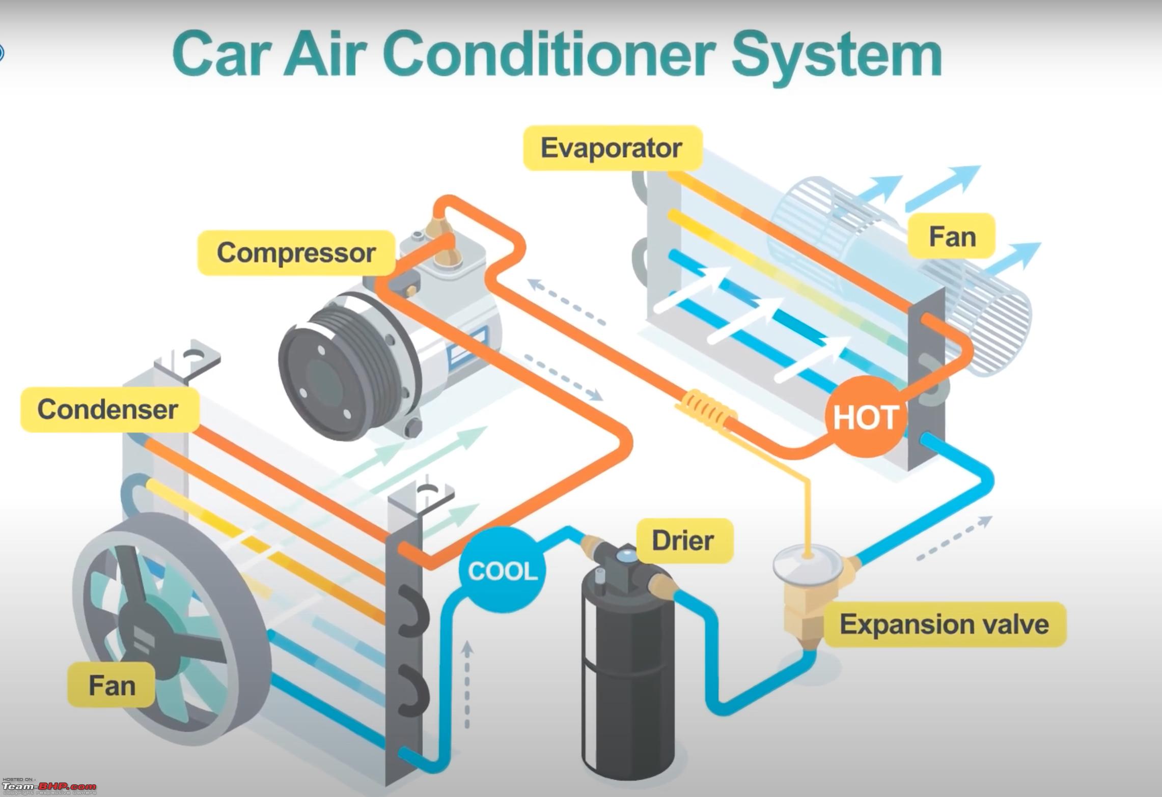 The compressor compresses (duh!) the refrigerant and pushes it through the condenser. The condenser is usually fitted at the front of your car, either in front or behind the radiator. With the help of a fan it is cooled down. Then cooled down, it is led through a drier absorbing any moisture. The expansion valves controls the amount of refrigerant flowing through the evaporator based on the upstream temperature of the refrigerant. The evaporator tends to be buried deep down in your dashboard. In essence that is all, in reality it is a bit more complex, but not by much. I don’t want to go into to much details/physics. Here is a good explanation on how your car AC system works, showing some more detail, Of course, these days on our modern cars the AC is controlled through various systems and has multiple sensor providing input (internal- external temperature, sunload (that little plastic blob on your dashboard close to the window!), various system pressures and temperatures. This is the functional diagram of the Ford Fiesta AC system. The same has been used since about 2012. It is probably a little more advanced now.  There are a number of different compressors out there. The main difference tends to be whether they have a clutch system or variable or a combination of both. Clutch only, you will find on older systems/cars (E.g. my Jeep and Alfa Romeo Spider). Combined clutch/variable is the most common variant these days. And the Fiesta has one of these. On a clutch only system the compressor clutch is activated based on the low pressure part of the system. it is an ON/OFF system. It’s fully on, or not. On most cars you will hear a very distinct “click” when the clutch engages. Depending on the system and the circumstance, your clutch will cycle on and off all the time, usually with an interval of 20-60 seconds or so. We will see in more detail how the variable compressor works. You will see that a variable compressor will run continuously, but the volume of refrigerant it pumps is controlled. The problem with this approach is that your variable compressor runs as soon as the engine starts, even if you are not using the AC. It will cause wear and it draws a little power from the engine as well of course. (negative impact on fuel efficiency) Also, some of the variable compressor did not last long when they were not used. As you will see, if they run without pumping the lubrication can become a problem. Especially if you begin to run low on refrigerant. (The refrigerant holds and circulates the oil as well! So that is why these days we tend to see clutch-variable compressors. Here you see the old and the new compressor. Guess which one we installed in the Fiesta and which one we’ll be taking apart! The big black pulley at the front also houses the clutch, you see an electrical lead with connector protruding. This is to activate the magnet that pulls the clutch in. On the bottom you see another black connector mounted on top of the compressor housing. It is actually on top of the control valve of the variable displacement mechanism as we will see.  You can also see a sort of yellowish and grey plastic bit held in place with a nut. these are just end caps to close off the inlet and outlet of the compressor and to ensure no oil leaks out during transportation.  It is important to know whether your new compressor has already oil in it or not. Each AC system takes a very precise amount of lubrication oil. So if the compressor is already filled, you need to add less. When filling, or rather recharging as it is known, the system, you add refrigerant with the correct quantity of lubrication oil and a dye. The dye allows for easy leak detection. In your car workshop manual it will mention how much oil needs to go in the system and also how much oil each main component will hold. (e.g. the compressor, the dryer, the evaporator etc.) So if you replace one component you have some idea on how much oil to replace as well Always good to check the type/model plate of your compressor. As you can see this is an original Ford Motor Company compressor. It was made in Hungary in 2015 and it takes R134A refrigerant. R134A is more or less the default type of refrigerant these days. 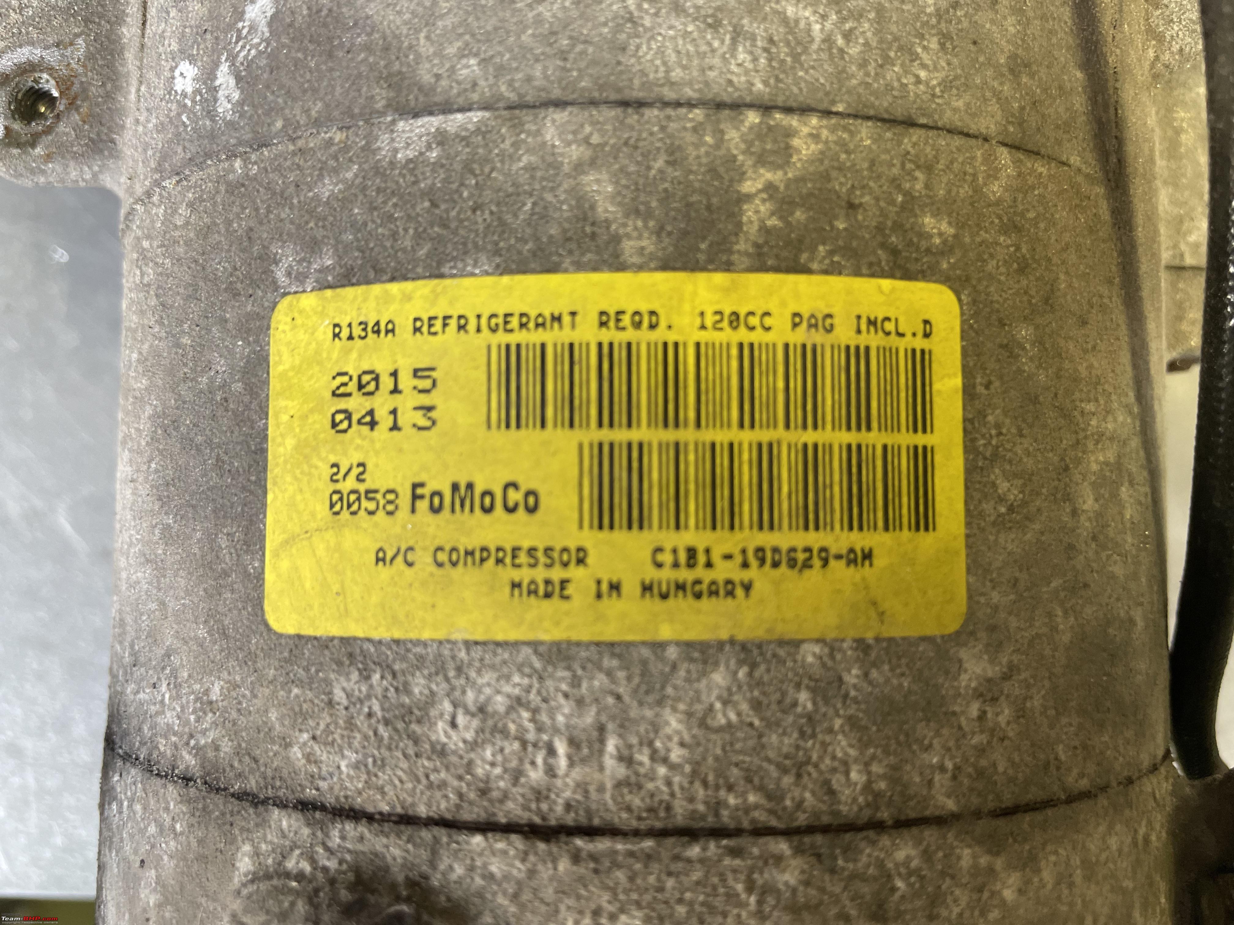 A closer look of the clutch at the front of the pulley:  Here you see that electrical lead going into the electromagnet. 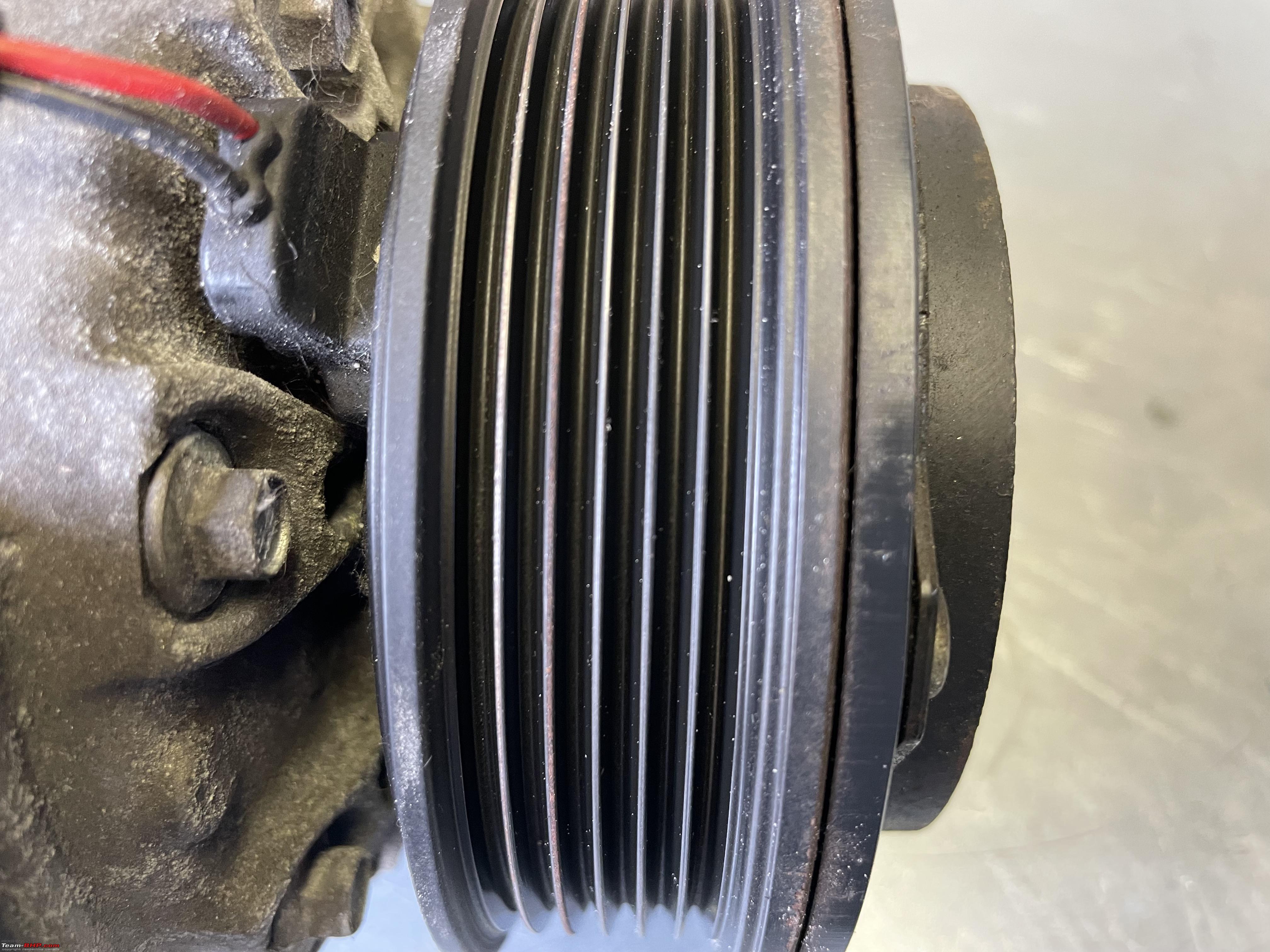 In order to take the pulley and the clutch off, that little bolt on the shaft needs to come off. Only way to hold the pulley was to put it in my vise and use a small socket to undo the little nut.  Here you see the inside of the clutch pate. When activated the electromagnet pulls it towards the pulley. So the clutch plate goes directly on the pulley! Notice the bearing in the centre of the pulley. Without the clutch being engaged, the pulley just free wheels and the compressor is standing idle, whereas the pulley still spins, driven by a V-belt, similar to your alternator. Notice that the clutch plate centre piece has splines on it, that fit on corresponding spines on the compressor shaft. So the clutch is attached directly to the compressor shaft, the pulley freewheel on the shaft, until the clutch engages.  The clutch plate seen from above. It is the actual clutch plate with a spring attached to a smaller plate. The electromagnet pulls the clutch plate and when it disengages the springs pulls it off the pulley. Only a few mm. The gap is a good indication of the wear of the clutch. On my Jeep I replaced the bearing and on an earlier Jeep I had to replace the whole clutch too as it was worn out. To thin and the electromagnet won’t be able to pull it against the pulley tightly anymore. 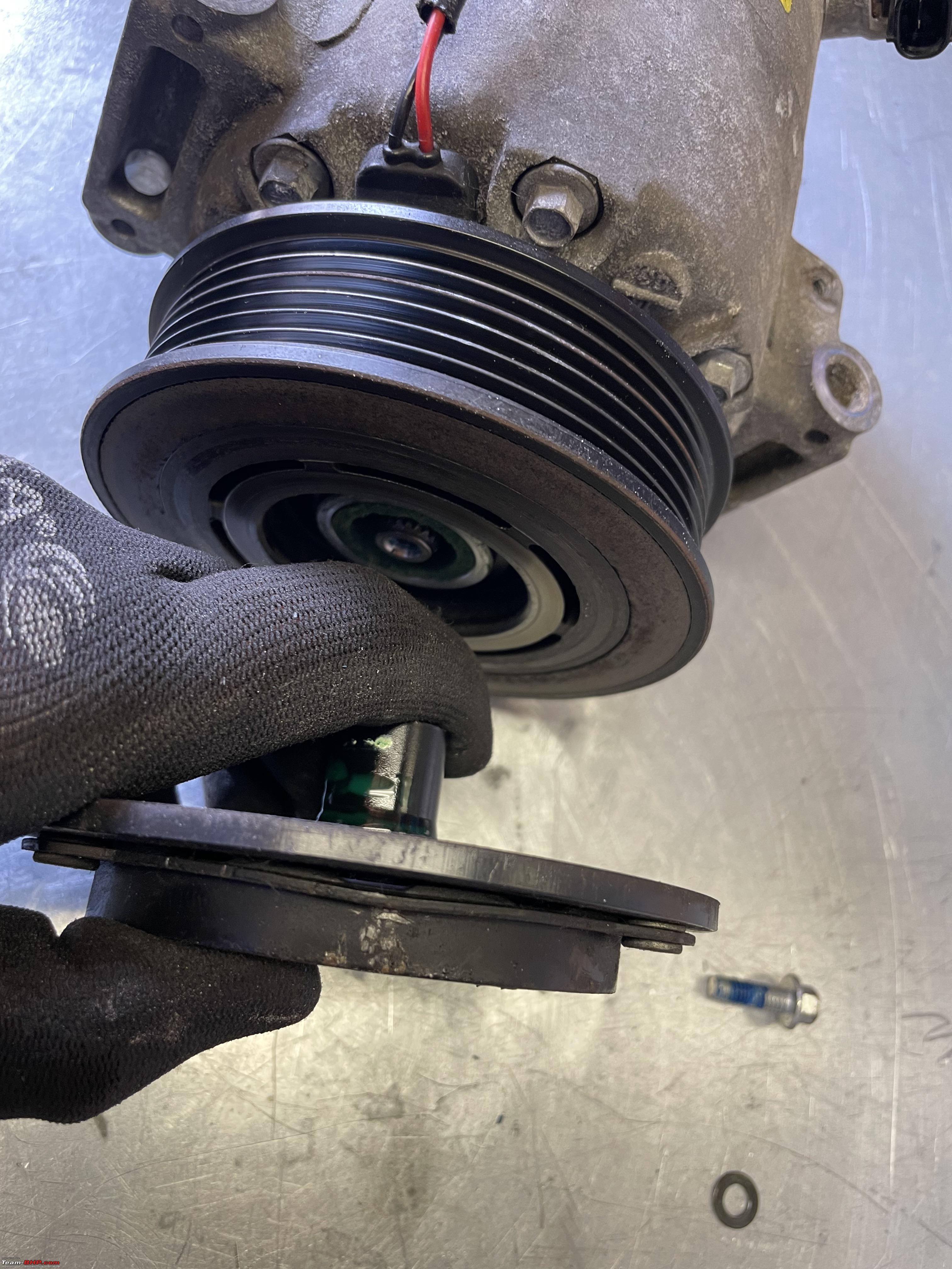 Here you see from right to left as I have taken everything off; The little bolt and washer that holds everything together, the clutch plate, a circlip that locks up the bearing on the pulley, the pulley with the bearing still inside. the rest of the compressor with on the right hand side the now exposed electro magnet. If anything wears out on these compressors it tends to be the bearing and or clutch. Bear in mind, when you don’t use the compressor the pulley is still running, so it is still wearing. Of all the AC jobs I have done over the years, bearing comes first, clutch comes second. (apart from filling the AC system). Luckily, replacing the clutch and or the bearing is fairly easy on most compressors. It rarely requires taking the compressor out of the car and thus no need to extract the refrigerant charge first. Check the links at the end of this post for the AC clutch bearing replacement I did on my Jeep.  A close up of that electro magnet. Notice the green felt. It provides what I believe is a seal against dirt and grime coming from the clutch. The clutch drive protrusion fits in here and is sealed, sort of by the felt 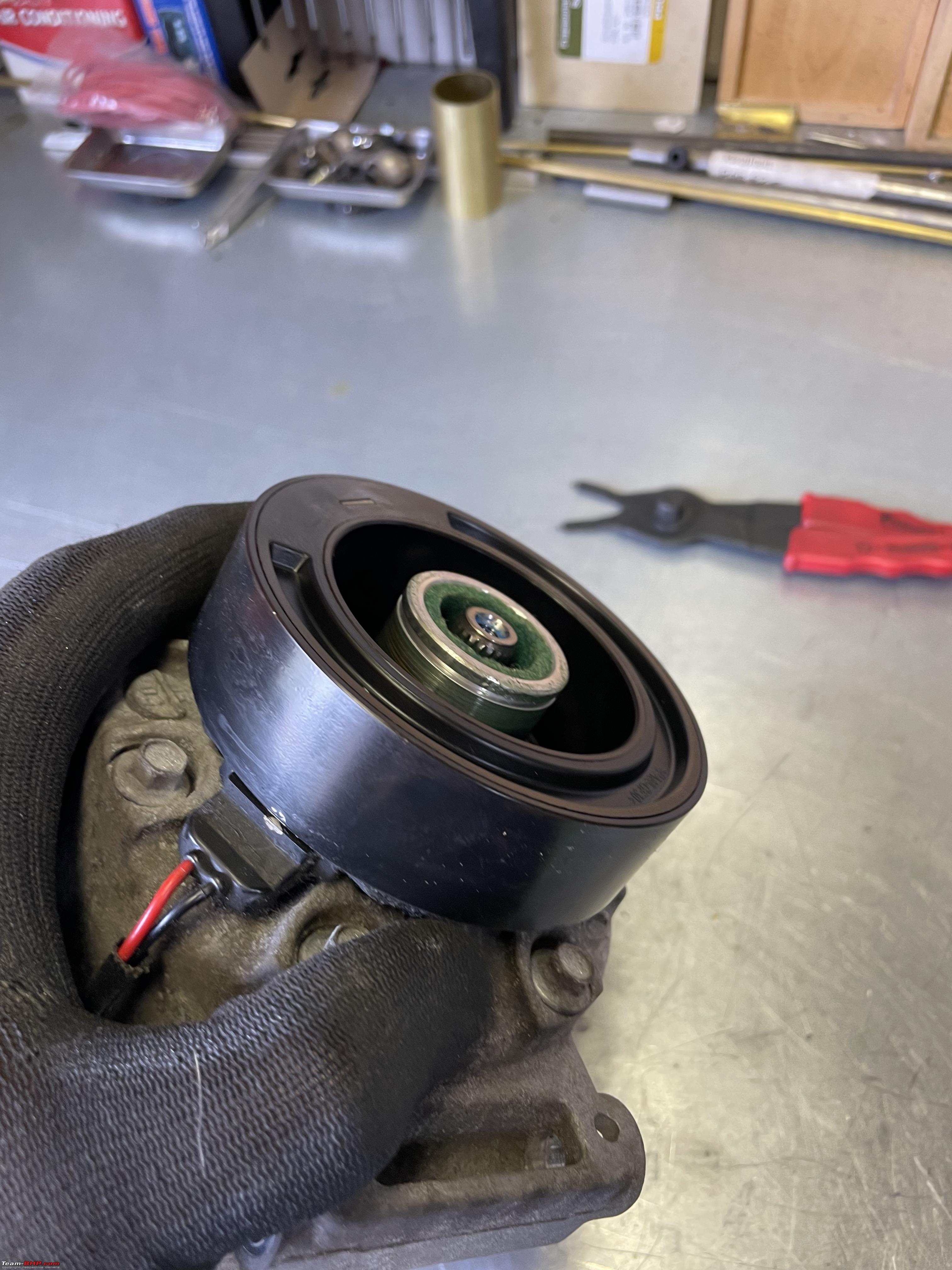 Same sequence as above, but now I have taken the electro magnet off as well. It is held in place with a circlip as well. Notice the green dye on the sprocket of the clutch? A tell tale of the leak!!!  Here we are looking toward the front assembly of the compressor. So everything we took off comes from this side. One thing you will notice is all this green gunk. That is actually lubrication oil and dye! So this where the Fiesta system developed a leak. A compressor will most likely leak in one of three places. Either the inlet or output pipe. This is usually an easy fix, you pull the pipe off, replacing the O-ring and that is usually it. However, the third option tends to be the most frequent one, a front seal leak of the compressor shaft itself. That is what happens here. That is how we determined this was the problem. We looked for the dye (with UV light it is even more visible) and around the front of the compressor was the only place where we could spot the dye. Notice the splines on the shaft. Now look at the images of the clutch plate, it has corresponding splines. So the clutch plate fits on top of the compressor shaft. There is a direct connection between the clutch and the compressor shaft. When disengaged the pulley freewheel freely (?) around the shaft. When the clutch engages, it locks up the (rotating) pulley against the compressor which is still standing still. Thus the compressor shaft starts to rotate. 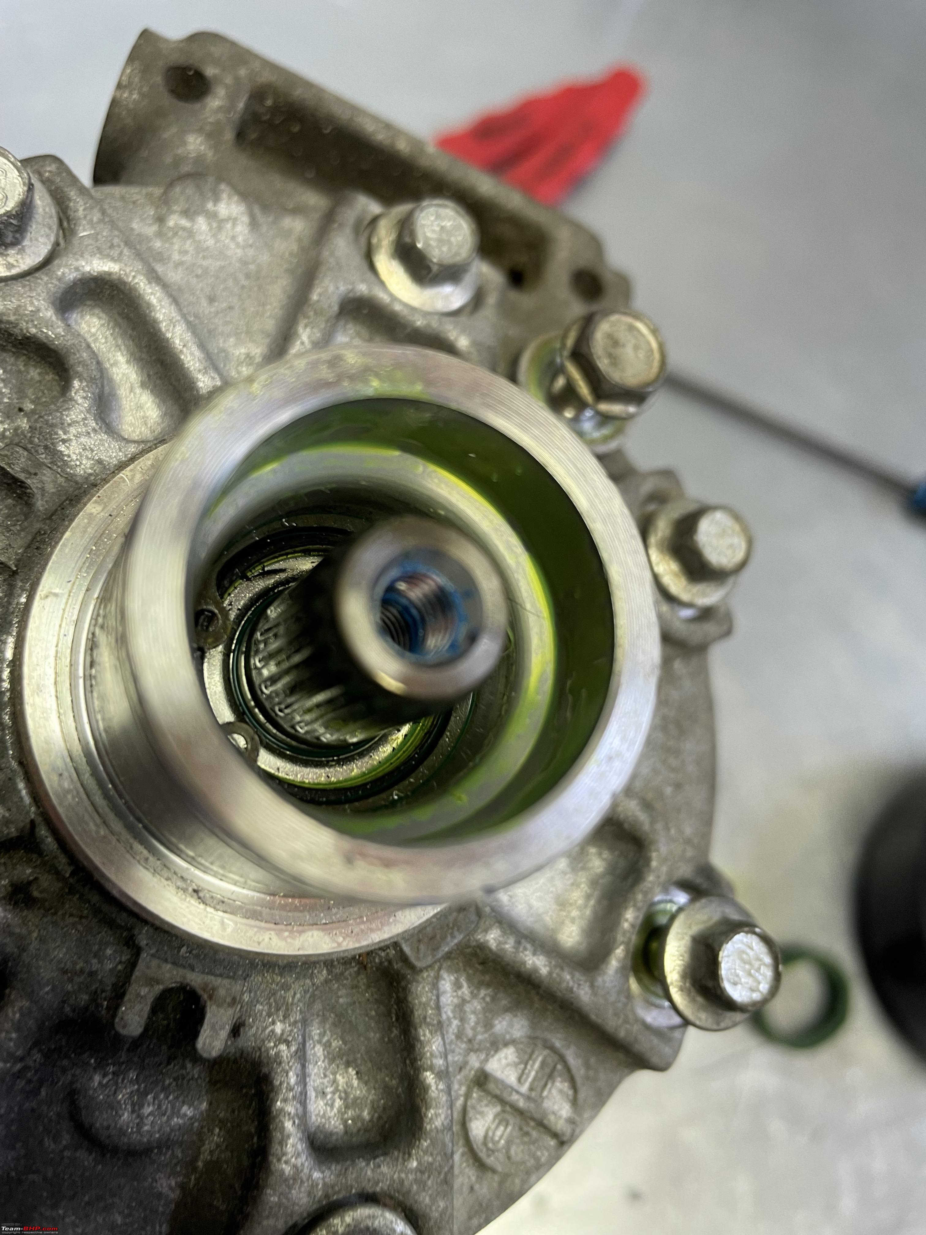 you will notice another bearing and circlip deep inside that recess at the front of the compressor. In theory you should be able to replace all of those. In practice, as you will see that is quite a complex and tricky job, requiring some special tooling. That’s why in the west everybody replaces a compressor with a leaking front seal. First of all, you are likely not to be able to get these individual parts very easily. Car manufacturers often use different compressors, so there is also a variety of spare parts out there. In addition, labour is expensive in the west. You also run the risk of replacing the seal, recharging the system and having to redo everything again if it is still leaking. So replacing is often the easiest and cheapest solution. These front seals do not wear out quickly. Actually, Jack told me that it was pretty unusual to see problems with the Ford AC compressors. Trust our bad luck. Our Fiesta is a 2015 and has done about 97K. That bearing/top of the seal has a special sort of felt piece around it. I am not 100% sure of its function, but I suspect to keep dirt and grime away from the bearing and the front seal. Just for extra protection. Would love to hear from somebody in the know.  With another circlip undone, we can start pulling the compressor body apart. There are three distinct different parts to it. I have pulled off one part. The middle part which has the cilinders in it is still attached to the rear which contains the control solenoid and some clever valve plates 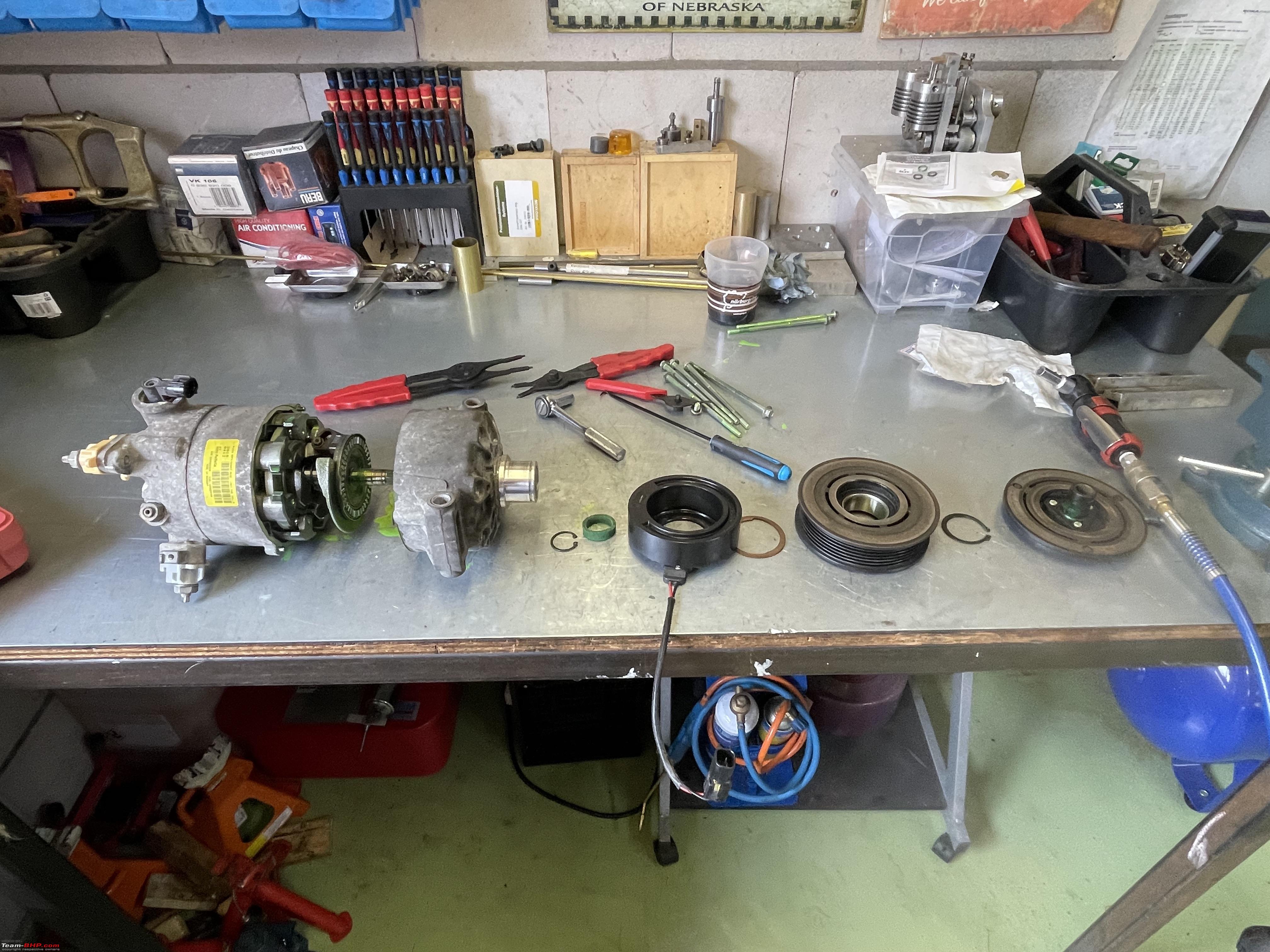 Here we are looking inside the top bit of the compressor I have just pulled off. You can still see the tiny little needle bearing and the main front seal is behind it.  I tried to pry the needle bearing and main front seal out, but as I mentioned at the beginning, that is not so easy. Basically I pulverised both, unfortunately. Now a far more complex and ingenious bit starts to show. This is the heart of a variable compressor.  It is important to get a feel for how this thing works. Which is a bit tricky by means of just images. Let's look at some of the parts and then at a video on how it all works. Here I have pulled the whole of all internals a bit further out of the compressor body.  Here the same bits but seen from a different position with the various names of the parts. 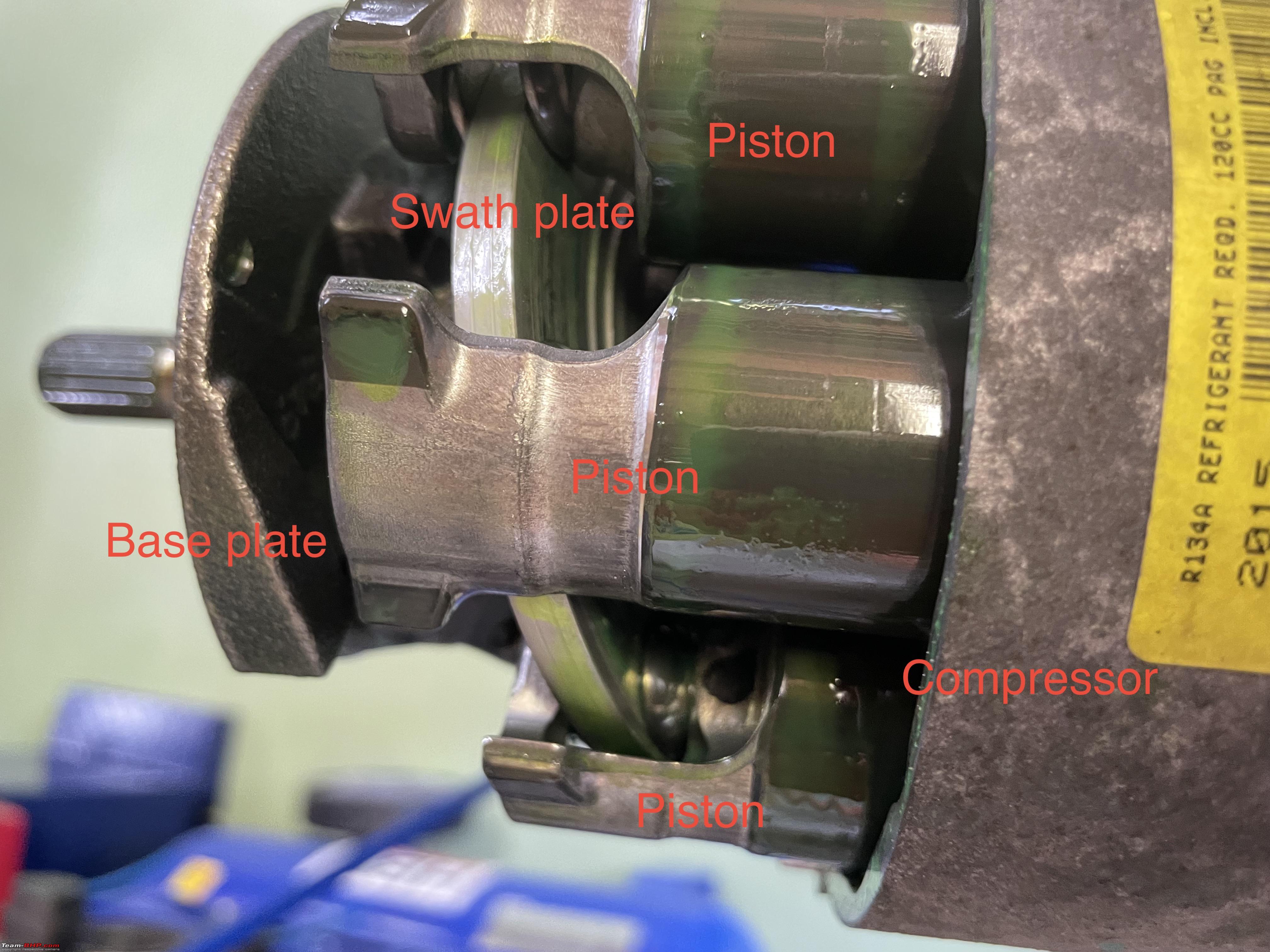 Here I have pulled the shaft with swash and base plate assembly and all the pistons out of the compressor housing completely! 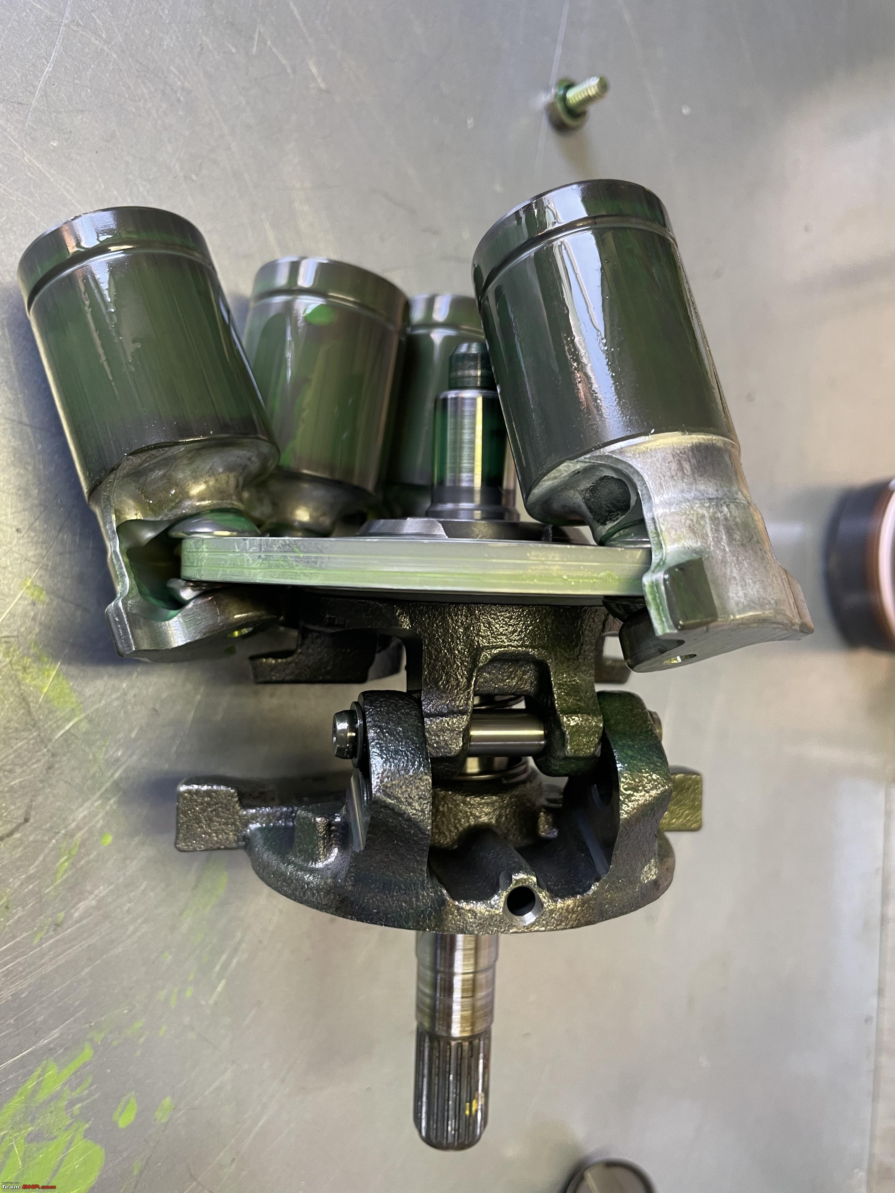 The middle part of the compressor housing, which encompasses the cilinders.  An individual piston. 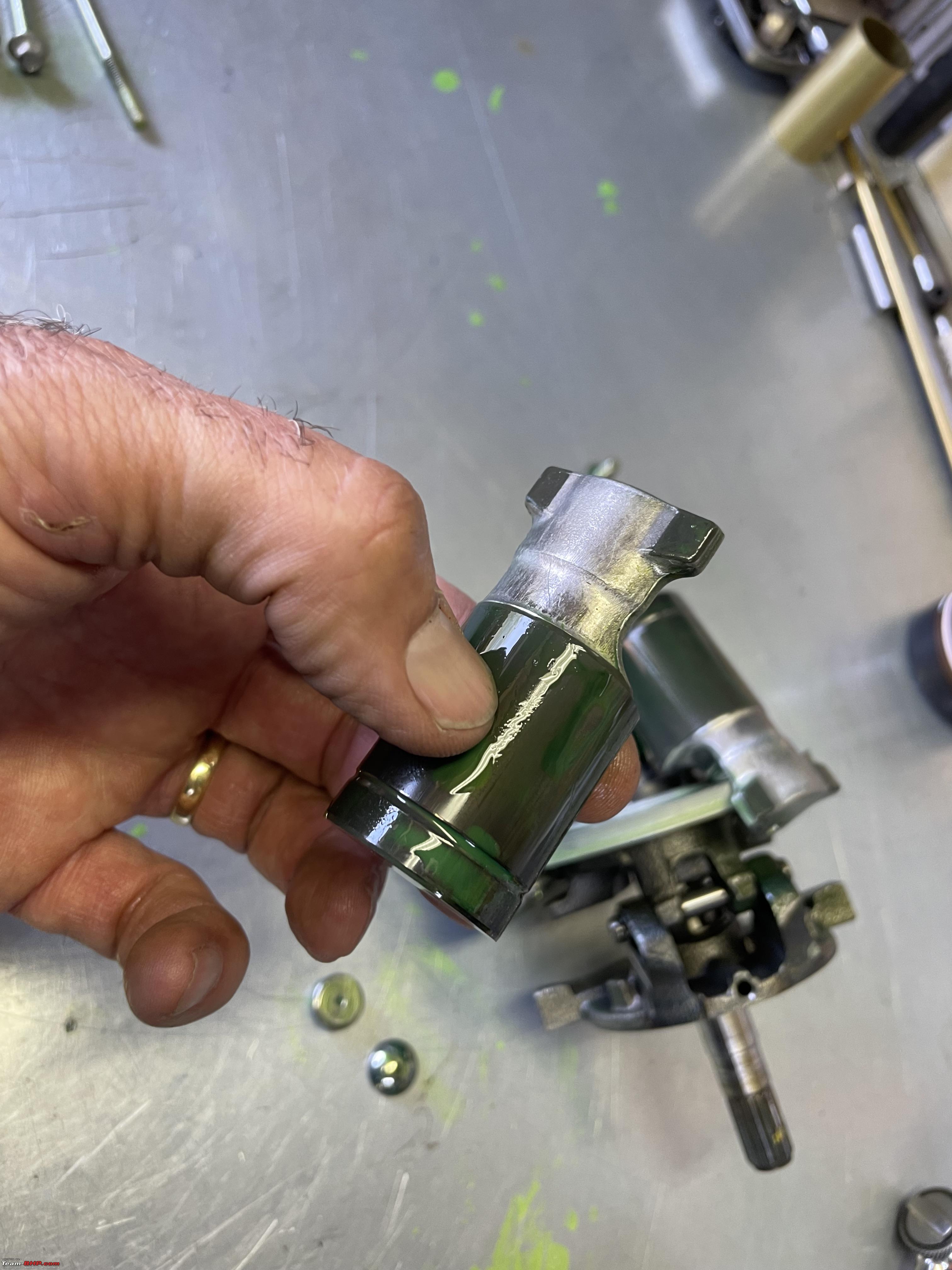 In order to get a feel for how all of this works I have a simple animated video. The basic principle of the variable compressors is that by adjusting the swath plate the piston start to move up and down in their respective cilinder. The more the swatch plate is tilted the larger the stroke and thus the volume displaced becomes. Last edited by Aditya : 10th December 2023 at 05:18. Reason: As requested |

|  (49)
Thanks (49)
Thanks
|
| The following 49 BHPians Thank Jeroen for this useful post: | acsandeep, aeroamit, aman9393, Anumon8448, ArijitGupte, Ashtoncastelino, Avikbrio, Bibendum90949, BleueNinja, Boo, chaotic, CzechItaliaMoto, DevilzzzzOwn, digitalnirvana, DrANTO, ERDOC, furyrider, GH0ST, GTO, HTC, Ithaca, Jaggu, jomson13, keroo1099, kryss.vectored, Meer, mrbaddy, Mu009, PearlJam, PGA, Potenza, rajaramgna, rajblr, Rehaan, S5157, sandeepmohan, sanjayrozario, shivraj737, Small Bot, sridhar-v, suhaas307, Taha Mir, Tgo, vaasu, venkyhere, vigsom, VijayAnand1, Vikram Arya, ysjoy |
| |
|
9th June 2023, 22:33
| #2 |
| Distinguished - BHPian | Re: Anatomy of a Car AC compressor (clutch/variable) I tried to make a little video on how the swathe plate makes the pistons move up and down. Or better; how the position of the swathe plate determines the stroke of the pistons. Notice when I just turn it, the swathe plate already moves the pistons a bit. The pistons never have no stroke. The main reason is to ensure some refrigerant and thus oil keeps circulating and some pressure remains. It is not a very good video Im afraid. The movement of the swatch plate is determined by the position of the electronic valve. It is actually the pressure underneath the piston that moves the swatch plate and thus all the pistons. The valve assembly at the bottom determine which piston get pushed up and which piston pushes out. Very clever. There are also variable compressors (and pumps) that have a sort of lever attached to the swatch plate which allows you to set the delivered volume very precisely. I found this video which does a much better job (hopefully) of explaining how this compressor works. Lets have a closer look at some of these parts I took out: At the top of this image you are looking inside the third and bottom section of the compressor. On the bottom the middle section, essentially the cilinders with the valve assembly still attached. Check the above video to see the working of the valves too. Notice the little dowel pins that ensure the three different sections of the compressor housing align perfectly!  The middle section seen from the other side as the previous image. You can see the cilinders.  Here I have just extracted the electronic valve. This valve, when energised or open, will allow (some) of the pistons to move the swathe plate.   A close up of the various parts that make up the valve assembly at the bottom of the cilinders. 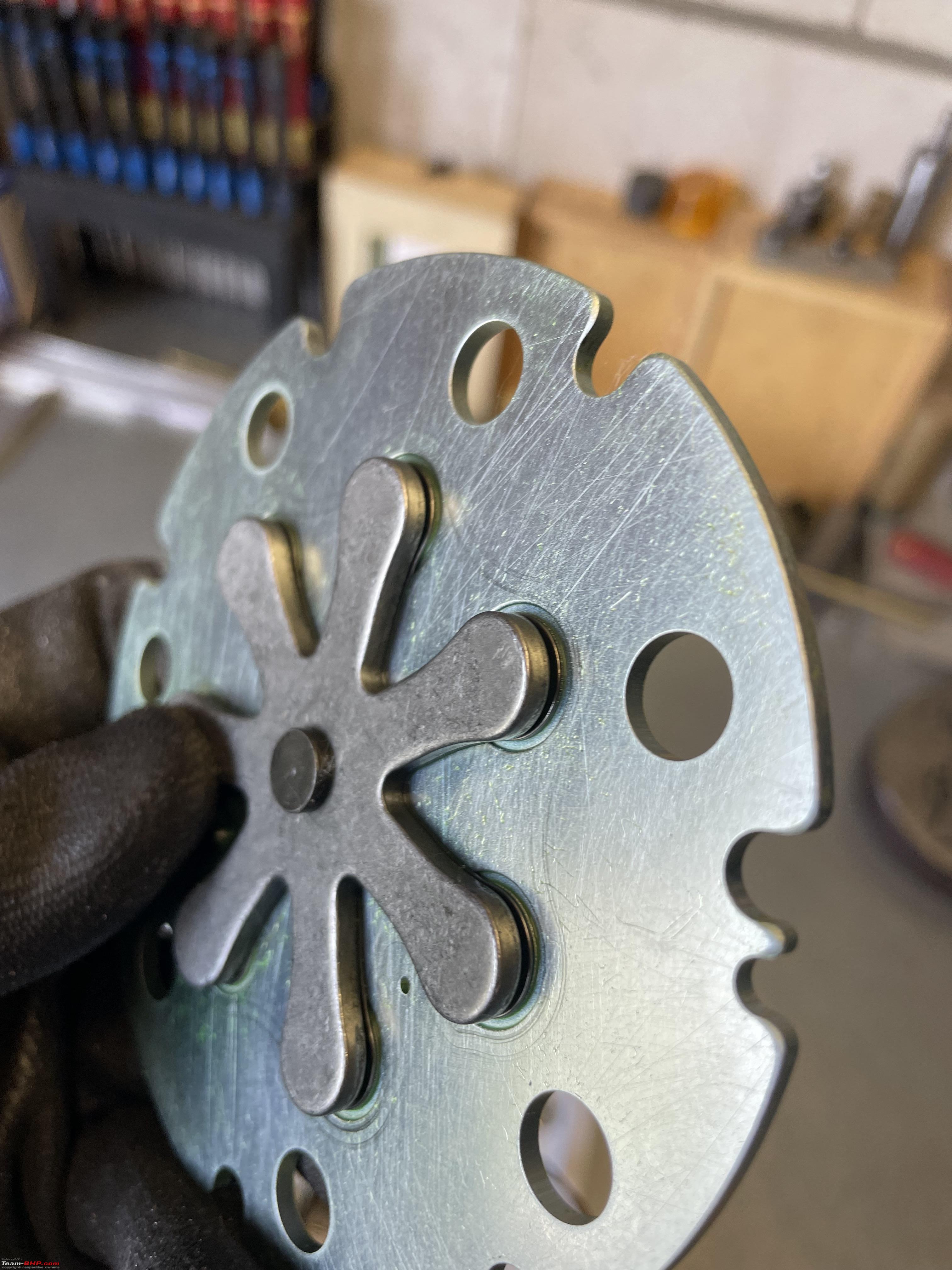  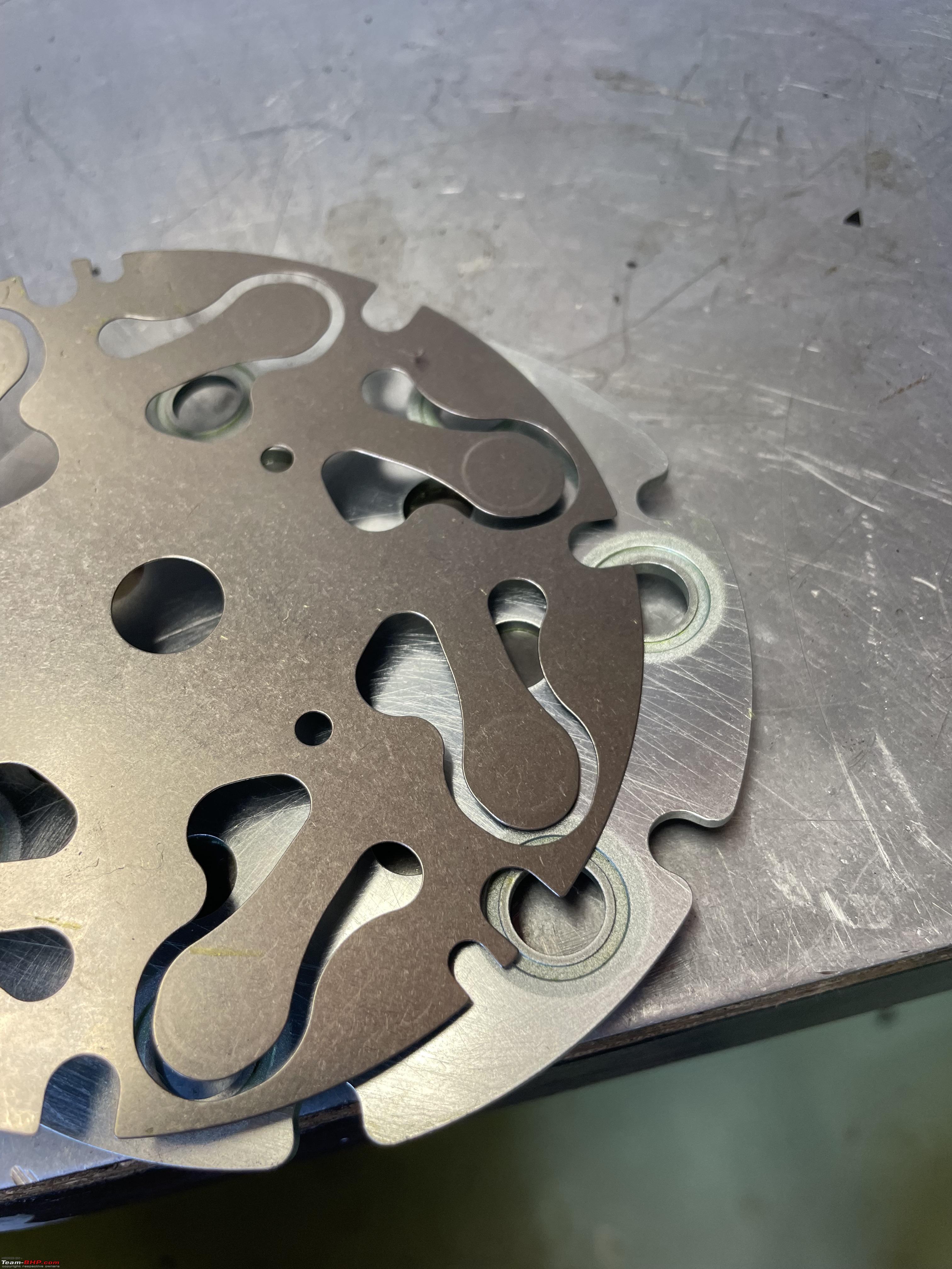 The complete shaft assembly with swathe plate, base plate, spring etc. 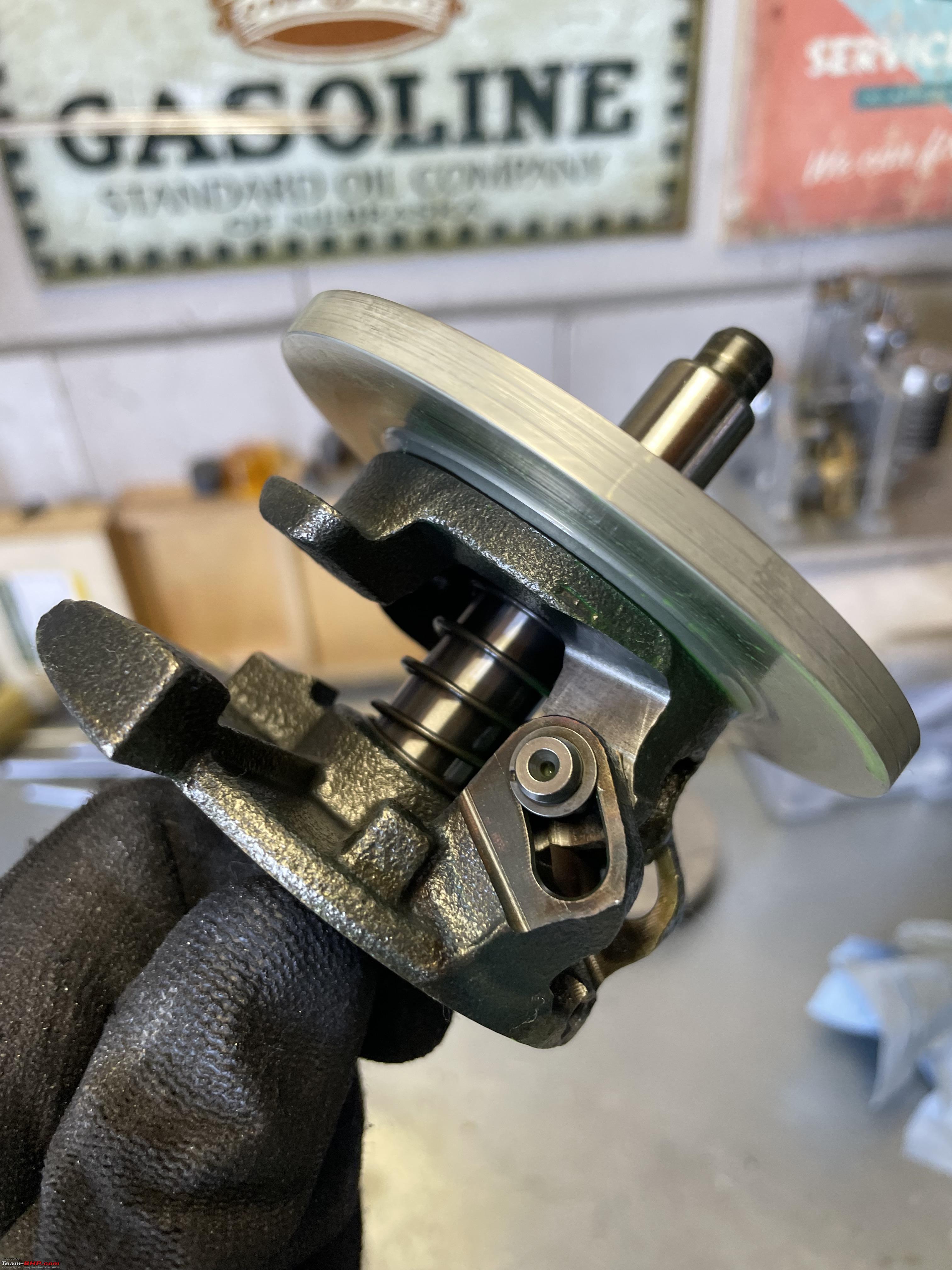 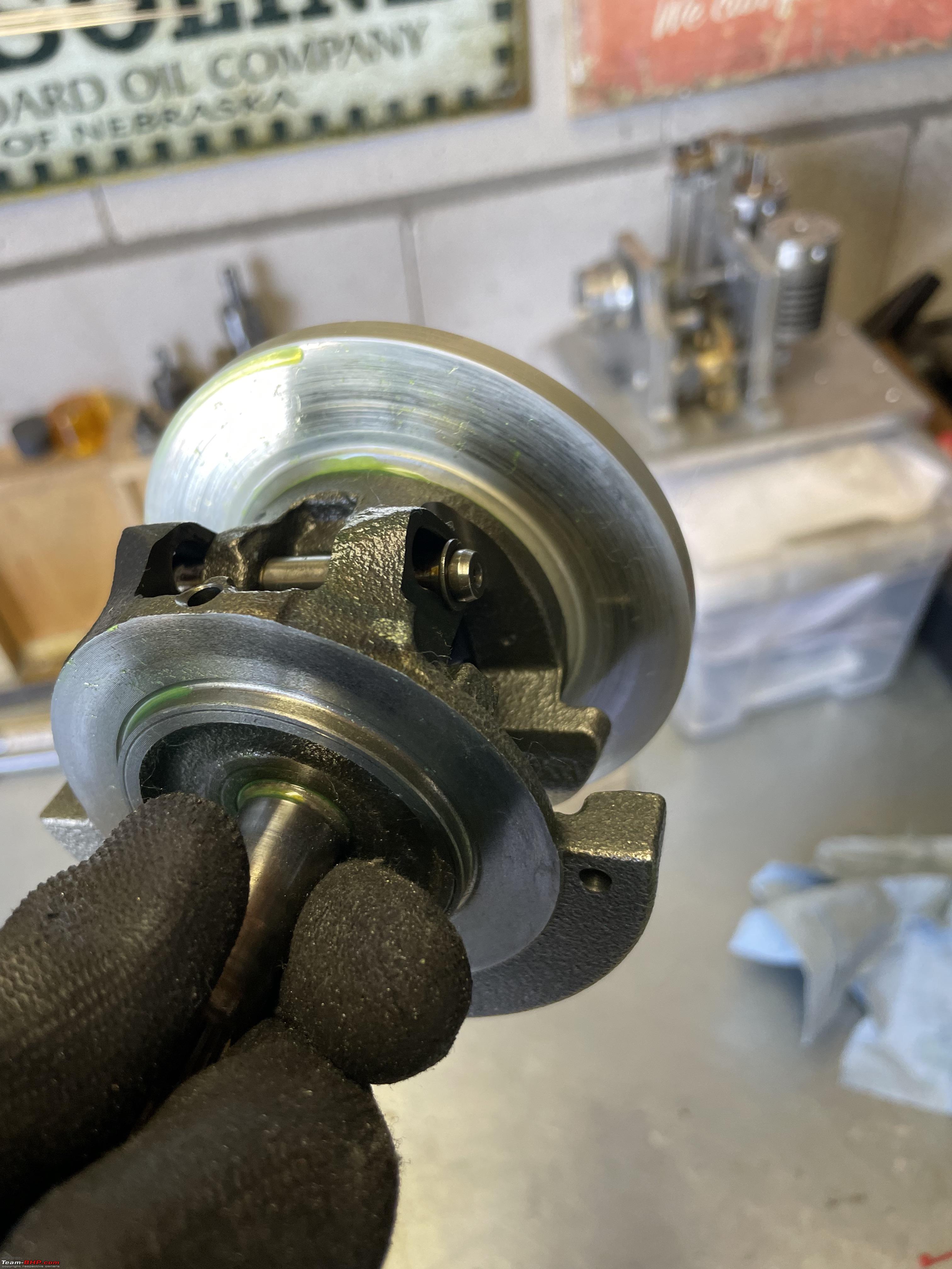 Here we have one of the piston. Machined from one piece of aluminium. As you will notice there are no piston rings. Which means the cilinder and the piston are made to very high level of precision. Probably around 0,01 - 0,02 mm play if not less! It also means that when you are running low on refrigerant, or worse, if the compressor runs without refrigerant, and thus no oil, the piston and or cilinder wall will get damaged very easily. The low pressure switch is supposed to prevent that. But can be easily by-passed during trouble shooting. Never ran a compressor at too low a pressure!! 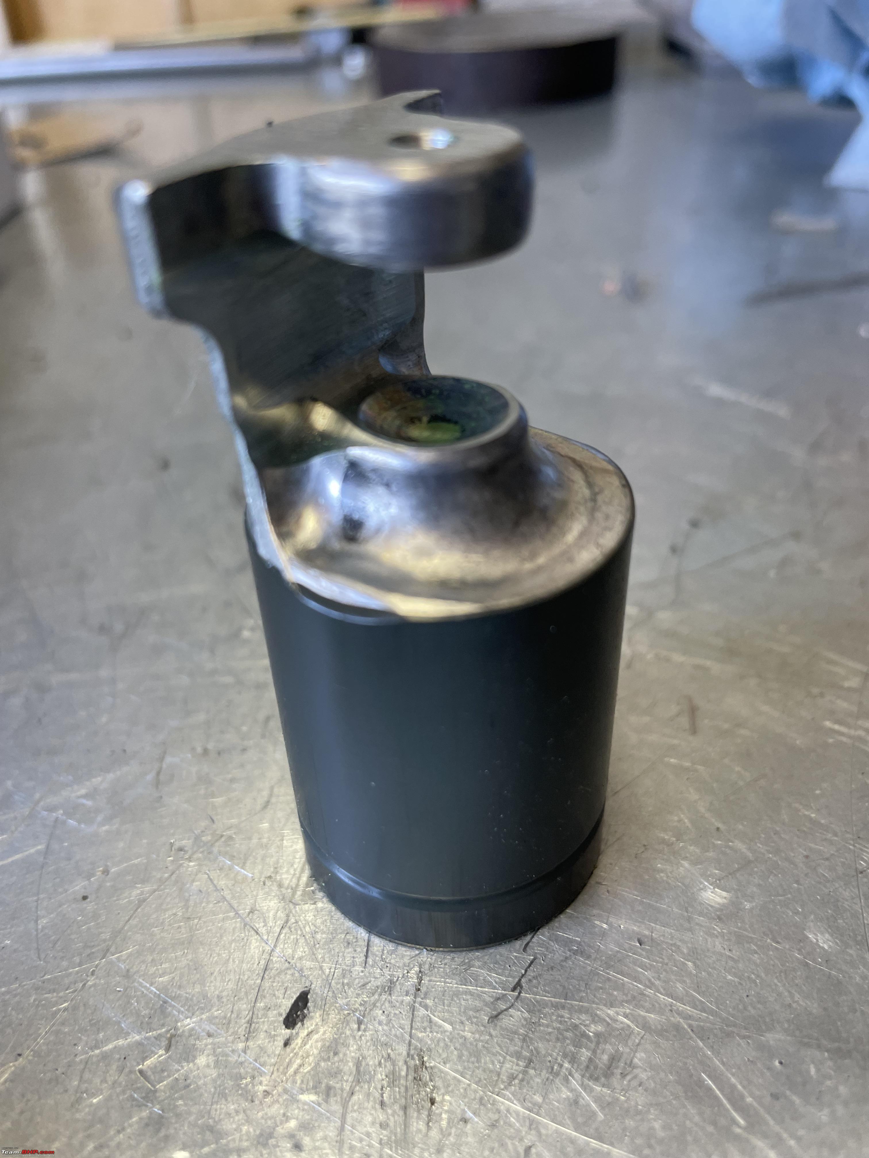 These little, sort of half ball bearings hold the piston in place on the swatch plate.  One on top, one at the bottom. That is all.   Two of the needle bearings that have come out.  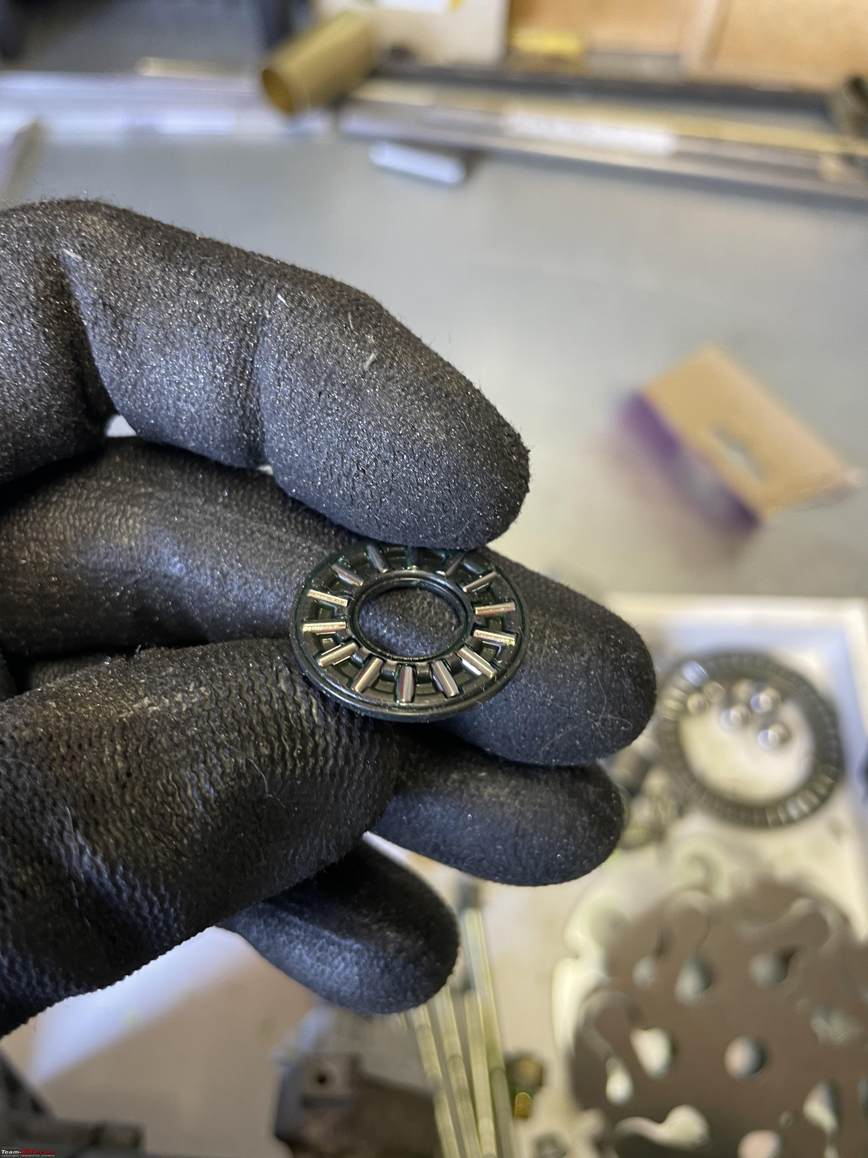 By now just about any part has been removed from the compressor. A workbench full of parts:  All sorted:  I enjoyed taking this compressor apart. I am always quite amazed at the precision of these mass produced parts. I have decided I am going to try to make this compressor into a cut-away-version, so it becomes easier to understand how it all fits together. I have seen a few example on the internet and Youtube. So I am milling away bits of compressor housing!!  A first look at a cut-away section.  It will take me a while before I finish this cut-away model. Once it is finished I will put it on the forum obviously! Just for references, a (short) list of the various AC jobs I have carried out on our cars in the last year or so: Replacing the Evaporator and dryer on my Jeep, lots of general information on trouble shooting and AC working too: https://www.team-bhp.com/forum/diy-d...ml#post5307858 Replacing the bearing of the AC clutch on my Jeep: https://www.team-bhp.com/forum/diy-d...ml#post5366709 Replacing the AC condensor on our 2015 Ford Fiesta: https://www.team-bhp.com/forum/diy-d...ml#post5325516 Replacing the AC compressor on our 2015 Ford Fiesta: https://www.team-bhp.com/forum/diy-d...ml#post5561187 Last edited by Jeroen : 19th June 2023 at 14:51. |
|
| (55)
Thanks
|
| The following 55 BHPians Thank Jeroen for this useful post: | --gKrish--, abhijeetp, acsandeep, aeroamit, Altima, aman9393, Anumon8448, ArijitGupte, ashivas89, Ashtoncastelino, astrodex, Bibendum90949, Big_Turbo, BleueNinja, catchjyoti, CzechItaliaMoto, digitalnirvana, DrANTO, funkykar, goandude, GTO, Harjot37, Ithaca, Jaggu, jkt, jomson13, keroo1099, KickassPenguin, Kosfactor, lina, luukie, Meer, Mu009, NiInJa, Omkar, PearlJam, PGA, pjbiju, rajblr, RaviDBLR, Rehaan, Ritkon, Rocketscience, rr_zen, S5157, sanjayrozario, SilverSmoke, sole_rider, TorqueKnight, vigsom, VijayAnand1, wavingflag, Whiplash7, yoshimitsu, ysjoy |
|
20th June 2023, 05:13
| #3 |
| Team-BHP Support  | re: Anatomy of a Car AC Compressor (clutch/variable) Thread moved out from the Assembly Line. Thanks for sharing! |
|
| (2)
Thanks
|
| The following 2 BHPians Thank Aditya for this useful post: | digitalnirvana, GTO |
|
20th June 2023, 09:22
| #4 |
| BHPian Join Date: May 2021 Location: Trivandrum
Posts: 114
Thanked: 587 Times
| Re: Anatomy of a Car AC Compressor (clutch/variable) Great thread sir. My BMW GT was having AC trouble recently and I was planning to read up on what type of compressors are used. My bet was on rotary type. Fun fact: These swash plate type compressors are variable displacement type whose output can be varied by altering the angle of the swash plate. These are used as pumps in the steering gear systems of most modern ships. The output is varied from Positive max to negative max by altering the swash plate angle using electric actuators which get their signal from the helm/autopilot. |
|
| (4)
Thanks
|
| The following 4 BHPians Thank Maverick_4662 for this useful post: | Bibendum90949, DrANTO, Jeroen, mugen_pinaki27 |
|
20th June 2023, 09:38
| #5 | |
| BHPian Join Date: Sep 2009 Location: Bangalore
Posts: 662
Thanked: 1,828 Times
| Re: Anatomy of a Car AC Compressor (clutch/variable) Thanks for the wonderful explanation and nice pictures! Had a novice question on this: Quote:
Thanks! Last edited by PearlJam : 20th June 2023 at 09:41. | |
|
| (3)
Thanks
|

| The following 3 BHPians Thank PearlJam for this useful post: | Jeroen, KickassPenguin, Rocketscience |
|
20th June 2023, 11:11
| #6 | |
| BHPian Join Date: Nov 2022 Location: Chennai
Posts: 38
Thanked: 105 Times
| Re: Anatomy of a Car AC Compressor (clutch/variable) Quote:
However, in this case, I feel that your text is going against what the diagram depicts. It seems the flow of refrigerant in your text should have been opposite. Not an expert, so I could be wrong too. | |
|
| ()
Thanks
|
|
20th June 2023, 12:23
| #7 |
| BHPian Join Date: Nov 2013 Location: Bangalore
Posts: 318
Thanked: 1,021 Times
| Re: Anatomy of a Car AC Compressor (clutch/variable) This is the anatomy of an ICE car's AC. For an EV, few things will change. There will be no clutch and the heating part will require a dedicated module using a resistive or heat-pump heater. In an ICE the heat will come from the engine itself |
|
| ()
Thanks
|
|
20th June 2023, 13:04
| #8 | ||||
| Distinguished - BHPian | Re: Anatomy of a Car AC Compressor (clutch/variable) Quote:
Usually on this set up the actuator does not move the lever on the swathe plate directly. There is a clever system of levers that ensures in effect a very simple control loop, so the swathe plate stops moving by itself after the rudder has turned. But there are also quite a few different mechanisms of moving a rudder. Variable pumps are used in all kinds of different application. Quote:
Here is an image from the Jeep. Obviously different car, some different design, but the basic principle still hold true. This big black box sits behind the dashboard. It holds the AC evaporator, the heater core and a number of valves that control the flow of air across either the AC evaporator, heater core or both.  Here the inside: The AC evaporator is the thing positioned horizontally, the heater core is fitted towards the top and is almost vertically. Just below it you can see the valve, or flapper that controls whether air that is blown to the cabin is also passing through the heater. The Jeep does not have a separate heater valve. So the cooling fluid from the engine passes through the heater all the time. So the valve needs to work properly!!  Quote:
Jeroen Last edited by Jeroen : 20th June 2023 at 13:10. | ||||
|
| (2)
Thanks
|
| The following 2 BHPians Thank Jeroen for this useful post: | PearlJam, rajblr |
|
20th June 2023, 13:10
| #9 |
| BHPian Join Date: Jan 2023 Location: Goa
Posts: 62
Thanked: 110 Times
| Re: Anatomy of a Car AC Compressor (clutch/variable) Thanks for the wonderful Informative post. I always knew it was closed loop. Now it has helped me understand better how the compressor works. To clear one of my doubt. It is safe to say the compressor parts are always working when the car engine is on ,and only based on the electronic activator the pistons do actual compression due to pushing it inward for compression to happen. |
|
| ()
Thanks
|
|
20th June 2023, 13:24
| #10 | |
| Distinguished - BHPian | Re: Anatomy of a Car AC Compressor (clutch/variable) Quote:
If you have a compressor with only a clutch, your compressor will constantly cycle on and off. Very often the compressor is very similar in construction as the variable one. The difference being the swathe plate is fixed, so the compressor always pumps, when the clutch engages. Just an addition, I had not mentioned before. Car AC system usually have a low temperature cut out set at around 4oC. So no matter what, the clutch simple will not engage at lower temperatures. Jeroen | |
|
| ()
Thanks
|
|
21st June 2023, 09:41
| #11 | |
| Senior - BHPian Join Date: Feb 2010 Location: Wellington
Posts: 3,283
Thanked: 6,045 Times
| Re: Anatomy of a Car AC Compressor (clutch/variable) Quote:
The compressor is automatically triggered when the car sensor detects a misty windscreen. Usually in cold weather. The physical AC electronic switch is OFF, however, the compressor turns on by itself, especially on a cold winter morning to demist. The compressor shut's itself off too, depending on the information relayed by the sensor. The only way I can force or cancel the compressor functioning is switching off the electronic climate control system. That means no air coming out of the vents. I do find the idea and build of the variable compressor sheer brilliance from an engineering perspective. It can regulate flow based on load more effectively than a non-variable compressor. Should be a lighter load on the engine too. I too had a knack of ripping things apart when I was a kid. Not at 3 for sure. Maybe closer to 10. However; I was not very good at putting things back properly. That said, my parents were patient and did not throw a fit of discouragement even when things did go wrong, which gave me encouragement and confidence to do the little DIY I do today. Much appreciate sharing this compressor tear down. Very interesting. Last edited by sandeepmohan : 21st June 2023 at 09:43. | |
|
| (1)
Thanks
|
| The following BHPian Thanks sandeepmohan for this useful post: | Jeroen |
| |
|
21st June 2023, 15:48
| #12 | |
| BHPian Join Date: Jan 2023 Location: Goa
Posts: 62
Thanked: 110 Times
| Re: Anatomy of a Car AC Compressor (clutch/variable) Quote:
| |
|
| ()
Thanks
|
|
21st June 2023, 19:14
| #13 | |
| BANNED Join Date: Mar 2011 Location: hump city
Posts: 1,293
Thanked: 5,891 Times
| Re: Anatomy of a Car AC Compressor (clutch/variable) Nice write-up, Jeroen, thank you for taking the time to pen this. I think there is a typo in your text : Quote:
compressor (further hottens and pressurizes hot gas) -> evaporator (absorbs heat from the air that's going to be injected into cabin) -> expansion valve (liquid to gas) -> condenser (rejects gas's heat to ambient and via cooling becomes liquid) -> compressor Shouldn't the correct path be : compressor (further hottens and pressurizes hot gas) -> condenser (rejects gas's heat to ambient and via cooling becomes liquid) -> expansion valve (liquid to gas) -> evaporator (absorbs heat from the air that's going to be injected into cabin) -> compressor ? | |
|
| ()
Thanks
|
|
21st June 2023, 21:22
| #14 |
| BANNED Join Date: Mar 2011 Location: hump city
Posts: 1,293
Thanked: 5,891 Times
| Re: Anatomy of a Car AC Compressor (clutch/variable) Jeroen, One basic Q : A) variable compressor with clutch B) variable compressor without clutch When A/C is OFF - in A, the 'gas+oil' is not circulating through the system, since the clutch is not engaged. - in B, the 'gas+oil' is circulating, without getting compressed (swatch blades are put to 'no compress' position), getting condensed into liquid by the condenser (assuming the main fan of the car gets switched on by the engine ECU), further expands into a gas through the expansion valve, passes through the evaporator without really getting heated (since A/C cabin blower is not running) and then gets back into the compressor; rinse and repeat the same cycle. Doesn't B suffer more wear and tear, because moving parts of the A/C compressor are moving all the time, even when cooling is not called for ? When A/C is ON - in A, what will the ACC computer decide to do, when the cabin temp has just reached the target number, and the computer now wants to wait for the temp to rise above a target+delta threshold, to call back the compressor into action once again ? Does it : (i) keep the clutch engaged but put the swatch blades into 'no compression' position OR (ii) disengage the compressor clutch. In other words, there will be a hysterisis window around the target temp, where the compressor doesn't need to work yet, how will the computer handle case A ? |
|
| (1)
Thanks
|
| The following BHPian Thanks venkyhere for this useful post: | Blooming Flower |
|
22nd June 2023, 16:19
| #15 |
| BHPian Join Date: Feb 2008 Location: Chennai
Posts: 37
Thanked: 68 Times
| Re: Anatomy of a Car AC Compressor (clutch/variable) Very illustrative explanation of fundamentals. Thanks for sharing. I face a unique problem in my 10year old Ecosport. The cooling is adequate while running in 2nd gear and above. But while in neutral and first gear, the compressor seems to be not working, the cooling drastically reduces and in case of extended duration in idling and first gear crawling, it starts blowing hot air. The Company service technical says the compressor needs to be changed. I am not convinced since the cooling is good while running. Can there be any other suspects to check? I do not want to change the compressor since I will be changing the car soon. Please give your expert opinion. |
|
| ()
Thanks
|
|