Vtec indicator installed.
First a little history of my misconception.
I used to think that vtec is a point where the cam geometry changes. It occurs when a hydraulic unit connects two different lobes of the cam shaft when is triggered by a solenoid. There is lot more to this, I am not trying to write a exposition on vtec, it has been very well documented on the net. Simply put, this results in the engine producing more power when vtec is activated. The vtec point is usually around 5000 RPM. Perhaps all this is true for older Honda vtec engines, but not so for the i-vtec or our R18A. This great piece of information never dawned on me till recently when I saw it in action, live. More on this later.
Now back to vtec indicator installation.
So my naive mind was fixated on a vtec point discovery when the engine is supposed to generate more power. I wanted to know when this occurs. So searched the net till I found two solutions. Both involved attaching a LED that can tell when vtec is activated or not.
1. Take the vtec pin from the ECU and attach a LED to that line.
2. Find the vtec solenoid, attach the LED to the electrical line connecting the ECU to the solenoid.
For R18A, finding the ECU pinout information turned out to be a impossible task. Found a few diagrams on the net, but was not sure if it was for the 2.0L Si or 1.8L R18A.
Finally found a link where a good hearted soul found the way to tap the solenoid line. I had to simply replicate his efforts. Here is the link
i-vtec solenoid wiring help - 8th Generation Honda Civic Forum
Now for some pictures.

The solenoid behind the valve cover. You can see the harness with two wires, the black wire with white stripe is the positive line. The line was used to take the leads.


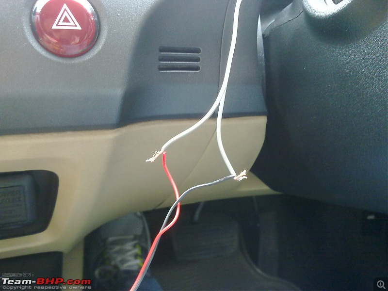
Initially we took the lead through the door and connected it to a multimeter to check if indeed we are getting on or off type signals. A TD was undertaken. There we found out that the line gets a signal of 12-13V during low load conditions. With aggressive driving, the voltage becomes zero.


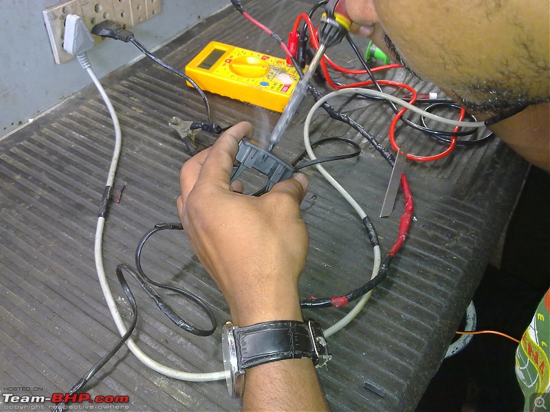
The dummy switch was used to house the LED. In these pictures the dummy switch is being prepared by burning a hole through the center and inserting the LED holder. The LED had a 1K resistor attached to it.

Final pictures from the engine bay. The solenoid harness looks like this now.

The wire was taken to through the firewall using an existing port which had a rubber cap.

The wire under the driver's footwell.

LED wire and solenoid's parallel connection being mated.

Final look of the dashboard.

A picture of the LED glowing during driving.
Driving impressions
The LED glows when vtec is activated. Found out that vtec comes on only during low load conditions. That is, irrespective of which gear is engaged, vtec is activated if only,
1. RPM is over 1500 and less than about 3000.
2. Very light throttle position.
So if you redline from idle, vtec is never activated. Thats why, if you rip the Civic, you never seem to trace that old vtec kick. Because there wasn't any kick in the first place. The R18A is designed to have vtec as a fuel saver, not power booster. The R18A is always in high power mode, when vtec is engaged it goes to low power/better economy mode. This is very different from other Honda engines, where the base level of the engine is in low power mode, after vtec it goes to high power mode. The same was always written on the "temple of vtec" article on R188A (the link has been posted a few times on the forum by several folks) and wikipedia. Never realized it till now.
So the indicator serves as a economy indicator. I am planning to test this on long term basis, specially during highway driving and check FE results with Vtec on or off.
P.S.: I also need to thank mdsaab for introducing me to this person who is pretty good with electricals and electronics. And Laluks and Sushrutha for encouragement.
 (26)
Thanks

 (1)
Thanks

 (1)
Thanks

 (2)
Thanks
 (2)
Thanks
 (1)
Thanks
 (1)
Thanks


 .
.

