Team-BHP > Shifting gears
Register New Topics New Posts Top Thanked Team-BHP FAQ


Reply
  Search this Thread
6,208 views
Old 12th March 2024, 17:34   #1
BHPian
 
Join Date: Dec 2005
Location: bang
Posts: 886
Thanked: 3,186 Times
DIY: Building A Vacuum Tube Amplifier

DISCLAIMER : VACUUM TUBES HANDLE VERY HIGH VOLTAGE (>300VDC) SO BE CAREFUL.

I've been in this forum for quite sometime now and considering that the amount of non automotive stuff is almost as high as the automotive stuff, I thought I would add something here. First up, if you are not a big fan of electronics, don't fret. I've tried to keep my narration as much non technical as possible.

Introduction:

I am from the solid state school of electronics. I'm familiar with terms like IC's, BJT (Bi Junction Transistor) and diodes. The vacuum tube era, typically between years 1900 - 1970, belonged to my grandfather. The invention of the BJT which technically started the digital era was in 1947 and as usual we were behind the technology curve. The first introduction to solid state electronics in many Indian households was in the form of "transistor" radios (60s and 70s). It was specifically called "Transistor" radios or simply "Transistor" purely to distinguish it from those old cumbersome wooden boxes called "Radios" which used vacuum tubes. This was followed by the B/W era of the television, which contrary to popular opinion, was in fact powered by solid state electronics. By the 90s, vacuum tubes were already history. So Kids these days have practically no idea of a vacuum tube or so I thought.

What is a Vacuum Tube?

DIY: Building A Vacuum Tube Amplifier-nv_1106_trinkaus_large.jpg

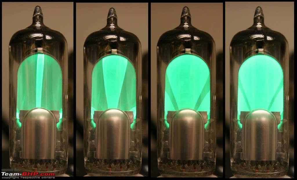
A Vacuum Tube or simple a Valve (Called VT For short) is the precursor to the present day Transistor (the BJT). It was invented somewhere in the beginning of 1900's when the first computers took shape. Though invented for calculations, it soon morphed into two main roles, Amplification and radio. A VT is glass tube with structured metallic sheets, filaments and few terminals which are used for control. It is also called as Thermionic tube since heat was the main source of its operation.

I'm not going into the technical details but here's a good video on how a tube works.


Why Vacuum Tube?

Connoisseurs choice. Period. Audiophiles swear that the sound produced by the Vacuum tubes are much truer to the original sound. Well, I'm not going to judge. The choice is up to you. The novelty factor is however very hard to miss. Tube amps are like vintage cars, few love them, few just don't care. A glowing tube which produces music in your drawing room is definitely going to grab those eye balls. My reason for getting into this whole "Tube Amplification" business was due entirely to my son who for various unknown and adolescent concerns, got into it. Peer pressure not being one of them.

Types of Vacuum Tubes

Well, lets see.

1. Diode - Only two terminals (Anode / Cathode ) used primarily to Bias.
2. Triode - Three terminals ( Anode/ Cathode/ Grid) used as an amplifier. It gets scarier from here.
3. Tetrode - Four terminals ( Anode/ Cathode / Grid / Screen). Wait its not over.
4. Pentode - Five terminals ( Anode / Cathode / Grid / Screen / Suppressor ).

Now you know why I prefer solid states over VT.

Terminologies associated with a Vacuum Tube (A little theory is not going to kill you)

1. Anode : The positive end of the VT. This is where the peak voltage is applied. Its also called Plate sometimes.

2. Cathode : The negative end of the VT. This is where the reference (Negative) voltage is applied. This is usually tied to the ground. All voltage measurements are wrt the cathode which is the source of electrons.

3. Filament : The element which produces the electrons in a cathode. The filament is wound around the cathode and heats it up to produce the electrons. European tubes use 6.3VAC as filament voltage while American ones use 12VAC. Talk of protectionism in pre war years.

5. Grid : Control part of the tube. The signal is applied here. With respect to the cathode, grid should be negative for proper Bias.

6. Bias : This is tricky. In order to get the VT into running mode, certain voltages needs to be applied to it. You can think of this as some kind of preparation of the VT. When properly biased, the VT is in conduction mode and any signal applied to the grid is amplified.


What is an amplifier? (You seem to be OK after the last section so a little more theory will not kill you)

Almost everyone here is familiar how an amplifier looks and what it does, I mean musically. Only now we will see the technical aspects of it. For easy understanding, we will use this block diagram.

DIY: Building A Vacuum Tube Amplifier-blockdiagramofamplifier.jpg

Theoretically, an amplifier (Vacuum tube or Transistor) will take a signal given to it and amplify the amplitude of the signal while maintaining its signal integrity. If the input signal is a sine wave then output will also be a sine wave of SAME FREQUENCY except with A PEAK VOLTAGE OF ITS COLLECTOR OR ANODE. Energy conservation holds in amplifiers too. You just can't expect a signal with a peak of 1.2V to be amplified to a 120V signal by just connecting it to a Vacuum tube. You need to provide it with that much power EXTERNALLY. All the amplifier does is change the amplitude of the incoming signal. Further, unlike what is shown in the block diagram, the output is 180 deg out of phase with the input signal.

Name:  Amplification2.svg.png
Views: 505
Size:  7.0 KB

If you see the above graph, the blue one is the input signal while the red one is the amplified form. Notice two things,

1. The blue and red signals are identical except for the voltages.
2. They both have the same frequency.

This is in essence the function of an amplifier.

Types of Amplifiers

There are various classifications of amplifiers.

Class A : Only one amplifier (VT or BJT) does the job. Simple but not effective especially when amplifying both positive and negative parts of the signal but a good starting point.

Push Pull : Consists of two amplifiers ( VT or BJT) one each for positive and negative parts. Very effective.

There are other configurations like class AB, C , D which are high power amps. For simplicity sake, we are going to build only a Class A VT Amplifier.

Audio Amp, Guitar Amp, What's the difference? (Tata and Benz what's the difference?)

Theoretically not much. Only Guitar amps need more "rock" distortion and the circuits and tubes are also different. They use devices like the "Wah Wah" pedal to achieve that. Ask that punk guitarist more since I'm not one of them.

Last edited by KarthikK : 25th March 2024 at 13:26.
srini1785 is offline   (22) Thanks
Old 14th March 2024, 15:00   #2
BHPian
 
Join Date: Dec 2005
Location: bang
Posts: 886
Thanked: 3,186 Times
re: DIY: Building A Vacuum Tube Amplifier

How to build it? (What didn't Kill you will strengthen you)

Part 1: Finding components

Before you build it, you need to first find it. A VT circuit needs some basic components like a center tapped transformer, resistors, capacitors (not electrolytic but paper type) which if you know where to look, are easy to find. For example in bangalore there is SP road and in Chennai there is Ritchie Street. There are shops in these locations who would wind you a transformer according to your specs. Finding the tubes is the hard part since these are long out of production. I know of some shops in SP road which stock them and a few online stores which have them but Caveat Emptor is the by-word for such purchases. So far I've had good luck. Bangaloreans are of particular advantage since BEL was one indigenous manufacturer which produced brand labeled VTs of either Mullard or GE designs and probably they still do. Scavenging parts from old radios and Gramophones, though not a civilized way, is probably the only way to source some very hard to find parts like output transformers as none of the city winders have any idea of how to wind a transformer for resistance rather than voltage. I once bought an entire gramophone from the Bangalore Sunday market just for the "Magic Eye" tube and won a lottery when the tube worked.


Part 2 : What tools do you need for the build?

1. A chassis: The chassis is what holds the components. Its usually made of a 2mm MS sheet and this sheet somehow needs to stand. So you can bend the long ends or fabricate a wooden box (like the one below) to hold the unbent MS Sheet. The tube is mounted with a tube socket that's roughly 20mm in dia. This needs to be drilled out.

DIY: Building A Vacuum Tube Amplifier-white-base-plate.jpg
DIY: Building A Vacuum Tube Amplifier-black-plate.jpg

2. An oscilloscope : Though not mandatory, it's good to have one as it shows the actual wave form unlike a Multi which only shows the RMS value. Not only for amplifiers, an oscilloscope is useful if you are seriously thinking of pursuing electronics as a stream (or hobby).

3. Date sheets of the VT : Mighty Important. All data sheets are available online, I suggest that you take a printout of them.

4. The usual orchestra: Multi, Soldering iron, wires, flux, wire-strippers, screw drivers, a good internet connection (in case something goes "phut") etc.

Your first build- Power Supply (Read the first line in this thread. Here on there is no turning back. Full volts apply.)

A good start would be to build a rectifier using the EZ80 tube. The circuit below produces a DC voltage of 250VDC and an AC of 6.3 V. This basic power supply set up is needed for almost every circuit. We built this as a separate piece of hardware as this can be reused with every other circuit that we build. For this you need,

1. A center tapped transformer with following specs :

Primary : 230VAC, Secondary 1. Winding 250V-0-250V, 2. Winding 0-6.3V. VT's are high voltage, very low current devices so the wattage of the secondary can be low, as low as 0.5A.

2. EZ80 tube with it's 9 Pin socket.

3. A 1A glass fuse and holder.

4. A 300V AC rated ON/OFF Switch.

DIY: Building A Vacuum Tube Amplifier-power-supply.jpg

This diagram shows full wave rectifier using EZ 80. In order for the valve to operate as a full wave rectifier, a center tapped secondary is required. The other tapping is for the filaments. This valve can be pictured as two diodes having a common cathode. Each anode of the valve needs to be provided with same voltages, hence a center tapped transformer. Values of Capacitors are 47 Micro F and Resistance is 4.7k (1/2W). The center socket is for taking the DC and AC volts out to the chassis which holds the Amp VTs.

The final assembly looks something like this

DIY: Building A Vacuum Tube Amplifier-final-assembly.jpg
Attached Files
File Type: pdf ez80-philips1953.pdf (100.0 KB, 46 views)

Last edited by srini1785 : 14th March 2024 at 17:12.
srini1785 is offline   (19) Thanks
Old 25th March 2024, 11:25   #3
BHPian
 
Join Date: Dec 2005
Location: bang
Posts: 886
Thanked: 3,186 Times
re: DIY: Building A Vacuum Tube Amplifier

Continued...

Once you have built your rectifier, check for the voltages. In the above circuit, the smoothing (Filtering) capacitors were not part of the rectifier circuit but they were built into the amp circuit in a different board. So when we check the volts it showed up something like this.


The 200VDC is for the anodes and the 6VAC is for the filament.

The actual Amp (This is why you are here)

We start with some theory. We've covered most part of it in the previous sections and now we will cover it bit more in detail. Components used in this circuit, save for the resistors, may be new to you so a little detail will be useful. First we unveil the most important part,

A. The circuit

We chose a simple Class A amp for this build. Objective was to build a basic amp set up which would deliver about 10W of power through a 4 Ohm speaker with clear amplification and least distortion. Idea was to create a prototype technology demonstrator rather than building a professional amp which can deliver thousands of watts. So, the circuit goes something like this

DIY: Building A Vacuum Tube Amplifier-tube-amp-schematic.jpg

B. The components

The above circuit uses the following main components (apart from the speaker and rectifier).

1. ECC83 pre amplifier.
2. EL84 Power amplifier.
3. Line matching transformer.

ECC83 (Also known as 12AX77) is a twin triode amp that is primarily used to amplify the signal. Inbuilt into a single tube are twin triodes which amplify the signal in two stages. In the above circuit, V1 and V2 are the two triodes which are encased in the single tube and observe that their connections are identical. The capacitor of 0.1MicroF is used to couple the two stages and the resistor 100k is used for biasing. The volts that is given to the anode is before filtering and its approx. 200VDC (Vss). The amplification done is this stage is not yet suitable for coupling to the speaker. Remember that the output signal is 180 deg out of phase with the input signal be it a Solid state transistor or a VT

EL84(V3) is the power pentode amp. This stage is what is used to couple the speaker. It has a high impedance and is able to deliver power to the speakers through a line matching transformer. It is coupled to a higher 240VDC (Vdd) which is obtained after the filtering (Smoothing) capacitors.

Line matching transformer(T1) is generally used only in vacuum tubes. Since these tubes have a very high internal impedance (order of a few Mega Ohms) a direct coupling between the EL84 and a 4 Ohm speaker would result in virtually no power transfer. The theory of power transfers between two devices states that the power transfer is maximum when their internal resistances match. As you may have observed, we are only talking about resistance and not volts when we discuss line matching transformers. So the key word is to match resistances through windings and not volts.

C. Observations

As you would have no doubt noticed that this circuit is a bare basic amp circuit with no onboard volume or bass or treble control. The volume is controlled externally. The idea was to basically build something which would faithfully amplify a signal with least distortions. You can add additional circuits once this set up is complete. The capacitors are paper type and not the electrolytic type for reasons beyond my understanding. Lets just say that VTs have their own idiosyncrasies.

D. Troubleshooting

Get yourself a voodoo priest. As if not hard enough to assemble the components and get the amp going, its more difficult to trouble shoot it especially if you are starting for the first time. We had to struggle for almost two months with multiple failures and setbacks before we at least got to this stage. One main problem is to get the bias correct. Gate should be at a volts negative to the cathode and if that is not properly done, you wont get anything out. Another problem is to find the correct line matching transformer for your tube. The transformer that we used was salvaged from a scrap radio and luckily it worked. Yet another problem is grounding. Make sure that the chassis is properly grounded. if any ground faults occur then it would affect the output.

Last edited by srini1785 : 25th March 2024 at 12:13.
srini1785 is offline   (13) Thanks
Old 25th March 2024, 11:36   #4
BHPian
 
Join Date: Dec 2005
Location: bang
Posts: 886
Thanked: 3,186 Times
re: DIY: Building A Vacuum Tube Amplifier

All said and done, this is the result.


No matter how much I tried, my Samsung mobile did not pick up the variations in volume. Trust me it sounds louder than what you hear and we are able to control the volume externally from our mobile.

The first observations was that at higher volume the distortions are more pronounced. Its because a single Amp (ECC83) controls the amplifications and it is not able to faithfully handle the amplifications but at lower volumes it seemed OK to us.

PS : As you may have noticed, I'm a tad inclined towards Illayaraja.
srini1785 is offline   (35) Thanks
Old 25th March 2024, 13:27   #5
Team-BHP Support
 
KarthikK's Avatar
 
Join Date: Nov 2009
Location: Bangalore
Posts: 2,638
Thanked: 10,974 Times
re: DIY: Building A Vacuum Tube Amplifier

Thread moved out from the Assembly Line. Thanks for sharing!
KarthikK is offline   (1) Thanks
Old 26th March 2024, 13:56   #6
BHPian
 
T-Bone's Avatar
 
Join Date: Nov 2015
Location: Bangalore
Posts: 85
Thanked: 222 Times
Re: DIY: Building A Vacuum Tube Amplifier

Quote:
Originally Posted by srini1785 View Post
All said and done, this is the result.

https://www.Youtube.com/watch?v=fCG4K3diFZE

No matter how much I tried, my Samsung mobile did not pick up the variations in volume. Trust me it sounds louder than what you hear and we are able to control the volume externally from our mobile.

The first observations was that at higher volume the distortions are more pronounced. Its because a single Amp (ECC83) controls the amplifications and it is not able to faithfully handle the amplifications but at lower volumes it seemed OK to us.

PS : As you may have noticed, I'm a tad inclined towards Illayaraja.
Only one word "B R I L L I A N T" ...

We too had an tube based radio when I was small and hence I can actually relate to your article.

One thing I always loved to watch in our radio was the green (radium colored) lamp that glows when turned on. I used to turn on the tube radio was just to see that light.

Is there a way to get that green lamp/tube ? Was thinking if I can use it as a night lamp. I know its not that powerful to use it as night lamp but just for the sake of the nostalgic feeling

Lastly, I too am a DIY kind of guy especially related to electronics. So, is there a way I can contact you for guidance in electronics stuff ?

Best Regards.
T-Bone is offline   (3) Thanks
Old 26th March 2024, 15:21   #7
BHPian
 
Join Date: Dec 2005
Location: bang
Posts: 886
Thanked: 3,186 Times
Re: DIY: Building A Vacuum Tube Amplifier

Quote:
Originally Posted by T-Bone View Post
One thing I always loved to watch in our radio was the green (radium colored) lamp that glows when turned on. I used to turn on the tube radio was just to see that light.

Is there a way to get that green lamp/tube ?
Those are called as magic eye tubes. There were two types.

1. Linear scale ones
DIY: Building A Vacuum Tube Amplifier-images.jpg
2. Pattern type
DIY: Building A Vacuum Tube Amplifier-634edc5fbb1d7210fd7cbbcb6e1pem806br5magiceyewith2.jpg

My understanding is that these are still produced and you can check in ebay or other such sites.

Quote:
Lastly, I too am a DIY kind of guy especially related to electronics. So, is there a way I can contact you for guidance in electronics stuff ?
Most of this stuff was done by my son but drop me a PM and i will try to help you as much as possible.
srini1785 is offline   (2) Thanks
Old 26th March 2024, 15:31   #8
BHPian
 
Join Date: Dec 2006
Location: Singapore
Posts: 72
Thanked: 110 Times
Re: DIY: Building A Vacuum Tube Amplifier

Nice to see a tube amp discussion on tbhp. I am big tube enthusiast myself but my interests are with two channel audio. I am what one would call an audiophile :-) My current amp is a line magnetic LM150 with new age KT150 power tube. The smaller ones are pre amp tubes.
Attached Thumbnails
DIY: Building A Vacuum Tube Amplifier-img_5244.jpeg  

ajitmoses is offline   (9) Thanks
Old 26th March 2024, 19:57   #9
BHPian
 
bobbyblr's Avatar
 
Join Date: Jun 2022
Location: Bangalore
Posts: 159
Thanked: 558 Times
Re: DIY: Building A Vacuum Tube Amplifier

Hi @srini1785,

I too had an urge to build an Vacuum Tube amplifiers in my college days.

I had built some audio amplifiers using ICs such as LM386, TDA2822, LM3886 and TDA2030. Never tried building Transistor or MOSFET based audio amplifiers because these needed a lot of understanding of the biasing techniques. My friend used to buy ready Hybrid audio amplifiers from Sanyo STK series. Later Class-D became more popular.

So where exactly did you got the vacuum tubes and the output transformers from ?
bobbyblr is offline   (1) Thanks
Old 26th March 2024, 20:08   #10
BHPian
 
Freespirit27's Avatar
 
Join Date: Feb 2022
Location: Mumbai
Posts: 136
Thanked: 334 Times
Infractions: 0/1 (7)
Re: DIY: Building A Vacuum Tube Amplifier

Nostalgic, reminded me of my Dad fiddling around with home made radios & amps. We used to have a fun time putting them - resistors, transistors, tubes, those analog intermeshing tuners and many thingys we never really knew what they did, into neat boxes once he allowed us to help him wind up. The slow buildup and winding down of the glow of the tubes were a sight. Much later in the physics classes also these components were so relatable.
You brought back great memories and the sounds I can imagine, are unreal, even if the phone cannot really pick them up. And yes the green eyes on the old radios
Even @ajitmoses's setup looks charming, I'm sure it must be a pleasure listening to it.
Freespirit27 is offline   (1) Thanks
Old 26th March 2024, 20:16   #11
Newbie
 
Join Date: Nov 2014
Location: Gurgaon
Posts: 10
Thanked: 26 Times
Re: DIY: Building A Vacuum Tube Amplifier

Lovely thread @srini1785. Very inspiring and brings back a lot of lovely memories during college and early career years.

I am a huge tube aficionado myself, although not mainly for home audio but for electric guitar amplification. My rigs were based on EL84 and EF86 tubes salvaged from old radios.

As you probably know, tube amps are especially suited for electric guitar amplification as when you overdrive them, the clipping is very soft as compared to a solid state amplifier. It also provides a natural compression effect. These aspects put together a very pleasing overdrive sound or crunch, that gives you that vintage guitar tone.

Trivia: Modern guitarists spend a whole lot of money in purchasing expensive guitar effect processors and DSP's to emulate that tube sound.

In pictures, The iconic Marshall Super lead 1959, Tube head which was Jimi Hendrix's favourite.

DIY: Building A Vacuum Tube Amplifier-images-6.jpeg

DIY: Building A Vacuum Tube Amplifier-marshall_1959_super_lead_100_reissue_back.jpg

Once again, thanks for sharing your build and I hope to get mine up and running soon.
Deepak George is offline   (3) Thanks
Old 26th March 2024, 22:46   #12
BHPian
 
Join Date: Oct 2020
Location: Gurgaon
Posts: 142
Thanked: 191 Times
Re: DIY: Building A Vacuum Tube Amplifier

Want to add a note: if someone wants to experience without DIY, you can buy online as well
dsr001 is offline   (1) Thanks
Old 27th March 2024, 12:37   #13
BHPian
 
Join Date: Dec 2005
Location: bang
Posts: 886
Thanked: 3,186 Times
Re: DIY: Building A Vacuum Tube Amplifier

Quote:
Originally Posted by bobbyblr View Post
So where exactly did you got the vacuum tubes and the output transformers from ?
There are a few stores in SP road in bangalore which stock them. You can try Vishal Electronics. They are quiet famous for student projects. There are some vendors in Pune too. I've not dealt with the Pune vendor directly.

The Line matching transformer is more difficult especially those suitable for tubes. I salvaged mine from an old radio.
srini1785 is offline   (1) Thanks
Old 29th March 2024, 12:55   #14
BHPian
 
sgmuser's Avatar
 
Join Date: Sep 2006
Location: Chennai
Posts: 771
Thanked: 1,207 Times
Re: DIY: Building A Vacuum Tube Amplifier

Amazing to see this simple looking but efficient DIY build. I too did a DYI of a bookshelf in MTM configuration (Zaph Audio kit purchased from Madisound US) which I am currently listening to while typing this in my home office setup. For the pre-amp I simply purchased a Ayima tube pre from Amazon US and use a Marantz PM6006 UK edition (somehow I find IR's music sound very good in this edition) as power amp. I mostly (99.99% ) listen to Ilaiyaraja and happy to meet a fellow IR fan!

Oh forgot to mention I have a Fiio Type-C Portable DAC attached to the laptop USB-C.

MTM kit link here.

Last edited by sgmuser : 29th March 2024 at 13:03. Reason: just to add one point
sgmuser is offline   (1) Thanks
Reply

Most Viewed


Copyright ©2000 - 2024, Team-BHP.com
Proudly powered by E2E Networks