3D Printing Classic Car parts
Even though VW bugs were built over a long period of time, there were changes made frequently and there are a lot of one-year only parts in these cars. Recently on TheSamba forum there was a discussion on an NLA plastic spacer used on the steering column of 71 super beetles. The role of this spacer was debated and it was NLA. Then someone posted a 3D file of this part. Since I had access to a 3D printer at work, I decided to try printing this part and see if it would cure a minor play that was there in my cars steering wheel.
So I downloaded the part and had it printed. Heres what it looks like.

This would be an easy experiment I figured. Just pull the wheel off, remove the turn signal and swap out the spacer. 30 minutes tops.
So, after work one day I removed the horn button and tried to remove the steering wheel. Only then did I discover that I was missing the 27mm socket that would be needed. So, this would have to wait, BUT, since I was looking at the horn, I figured Id remove the horn ring and clean the contacts. There was one position of the steering wheel where the horn would sometimes not blow. The horn ring is held on by these 3 screws. The 4th holds the wire that grounds and activates the horn when the ring is pressed.

I cleaned out the back of the horn ring where it contacts the steering wheel to complete the circuit and mounted the horn back on. A quick test to see if it had improved.
Actually, it was now WORSE. The horn would not blow at all. Uh oh! Perhaps the battery was run down? So I put the charger on it for a bit and then started the car still the horn would only blow occasionally. C&#P!! While installing the ring back, I had pulled on the grounding wire perhaps it was now loose? Now I needed to get that steering wheel off to trouble shoot and fix this.
A nice-to-do experiment had now become a must do repair.
A few days later I picked up a 27mm socket from JC road. Then took off the steering wheel. I first punch-marked both the steering wheel boss and the column shaft so that I could put it back together easily to the same alignment.

The turn signal is held on by these 4 screws. Remove those and the turn signal switch comes loose though still restrained by the wiring harness.

In this next pic you can see the plastic coupler. The original one was cracked and crumbling. Clearly there had been some repair done here in the past. The coupler was held together by winding fine wire around it. The wiring on the turn signal switch had been cut and then repaired with insulation tape I dont like these repairs. So now I will also need to fix the turn signal wiring harness at some point. Not today though since it works and Ive got enough scope creep happening.

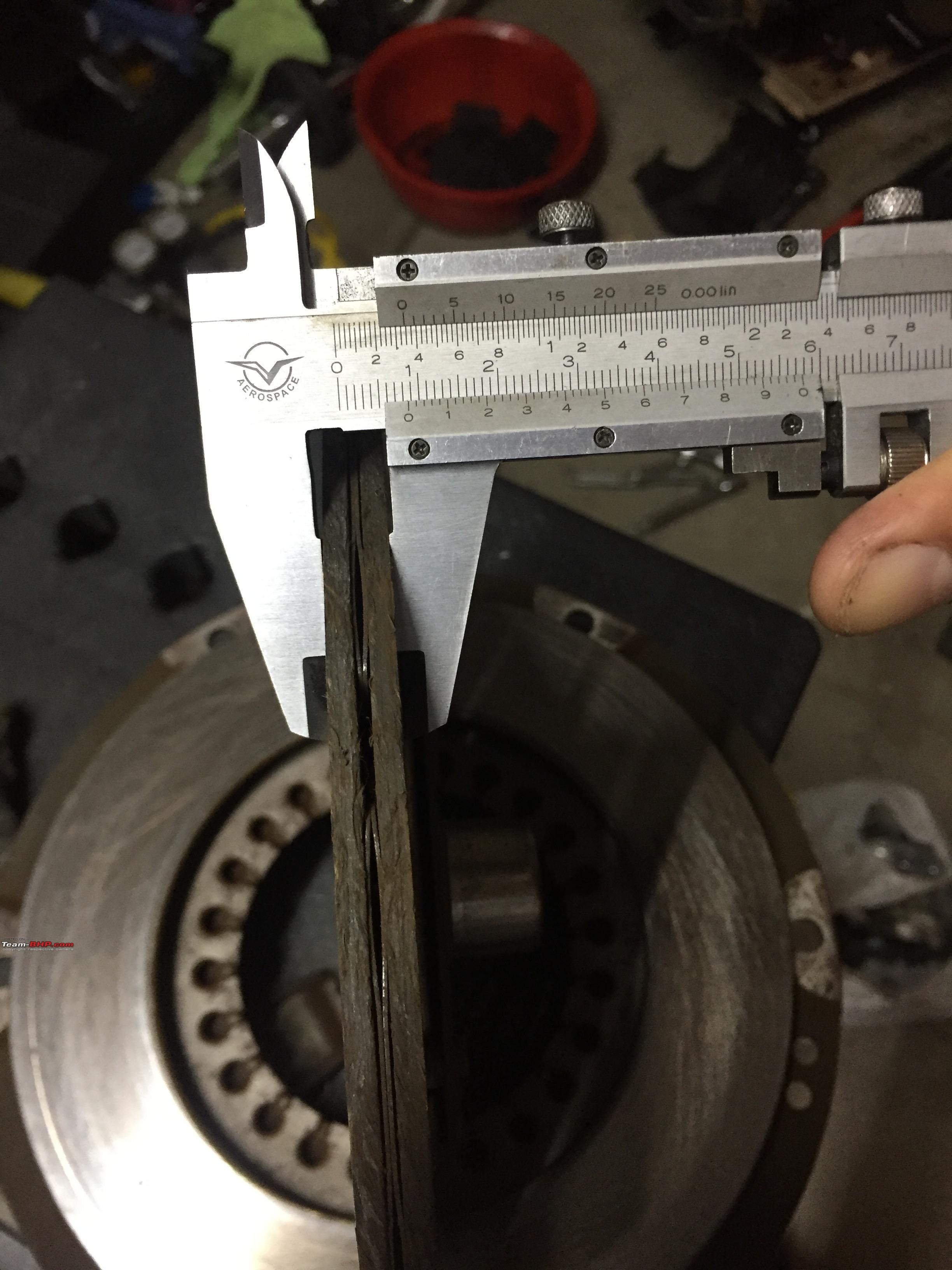
I checked out the bottom of the steering wheel theres a turn signal cancelling ring which also has a contact ring and the grounding wire is soldered to this ring. This ring was corroded and worn thru in places. The wire was firmly attached though. So I cleaned up the ring as best as I could. And since I had the wheel off, I also removed that circlip and replaced the old spacer with the printed one. While the dimensions were mostly ok, the wall thickness of the original was a bit more (1.7mm vs. 1 2mm). I can fix that in the next version if needed.


Then I started reassembling. Once I got the turn signal mounted back on I fitted steering wheel back on without tightening and tested the horn to see if it was working now.
The moment I turned the key to the ON position, I heard some crackling sounds of sparks I had a short somewhere!! Was it on those poorly repaired turn signal wiring? I took the switch off once more and test each circuit with my multimeter. They were all ok. Put it back on once more. Tested again. Same result. But, I was able to narrow down the source it was the ignition switch.
Damn! This repair was heading downhill fast and the number of items needing fixing growing fast.
These ignition switches are known to fail. But again, another one year only part which meant either fixing this one or modifying one from another year/model to work. So I started figuring out how to remove the ignition switch from the steering/ignition housing. As I pulled it out, it became clear why there was shorting the electrical part of the ignition switch which is at the bottom of the switch had come apart and shorting. In order to repair this part (or try), Id have to pull out the entire turnsignal and ignition harness all the way back to the fuse box. And also pull off the steering housing. Even then, I had to then remove the sleeve on the harness to separate the ignition and turn signal portions so that I could pull out each from the housing.
Housing with still attached Turn switch and ignition. The bottom portion of the ignition switch has come off.

Cutting apart the harness sleeve to remove separate the ignition and turn signal switches. (I should have tried harder to just slip off the sleeve instead of cutting it.

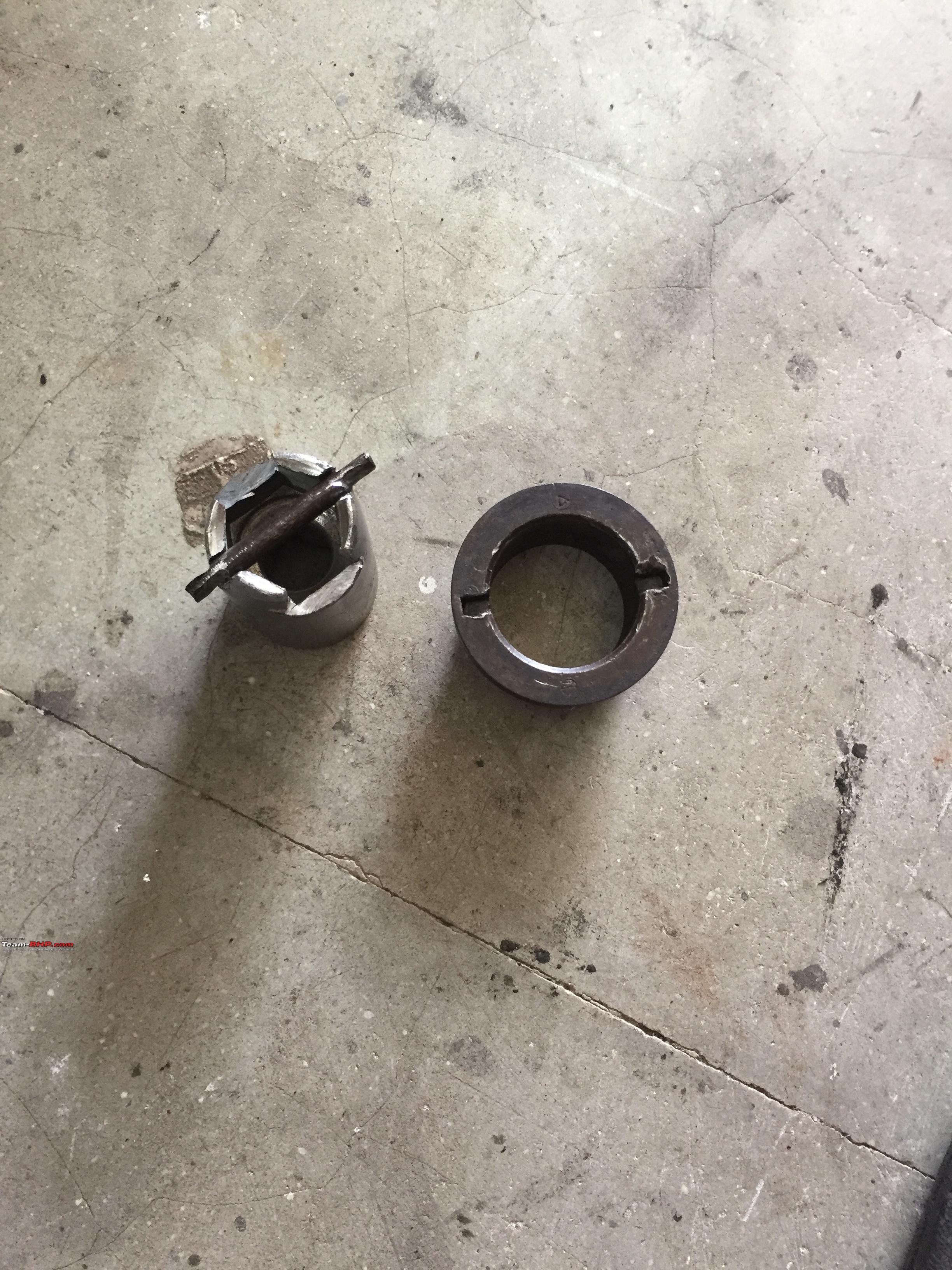
Separated.

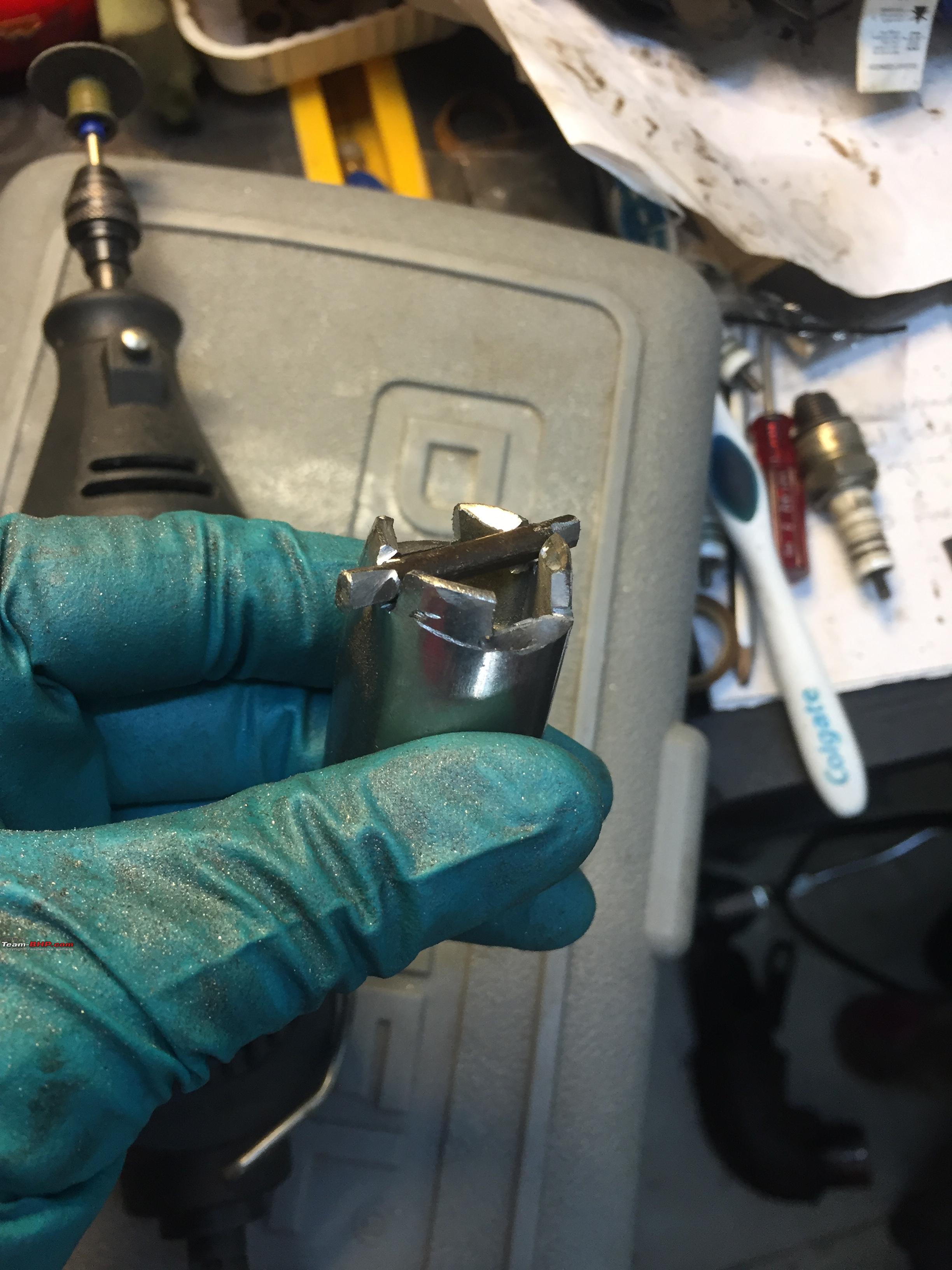
Heres the empty casing for the electrical part of the switch.

Reassembling:

This brass wiper needs to remain in the correct position when reassembled or it will cause shorts. This was hard as there were those small springs underneath and nothing to keep this one in position.

These crimps had come off and allowed the plastic end cover with the wires to come free of the housing. Putting this end cover back on without moving the brass wiper in the above pic was tricky. But I managed to in the end.

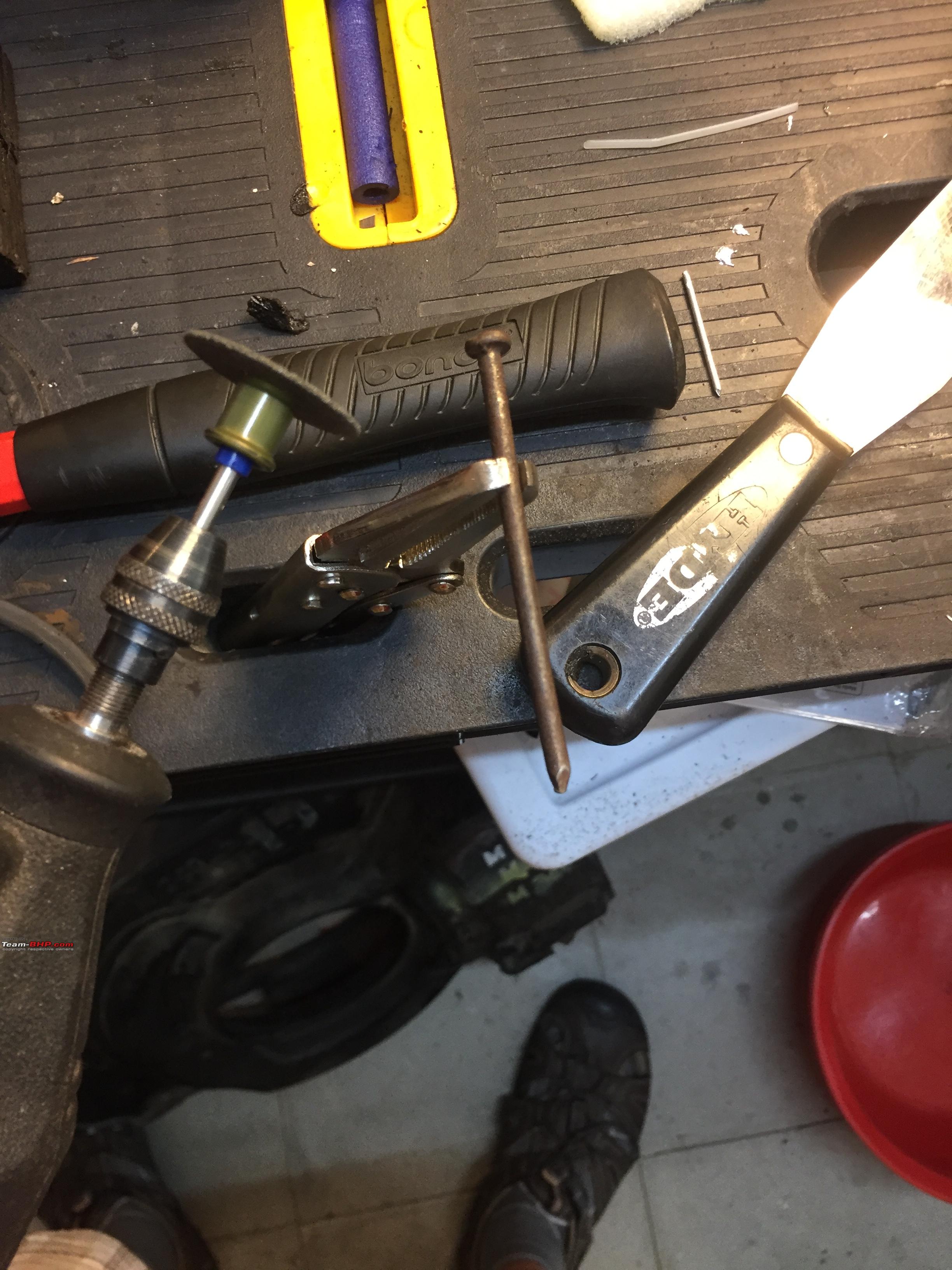
Once I got that end cover back on, used some clamping pliers to hold it in. Then used a drift and hammer to make the crimps better.


I now tested the switch with a multimeter. The readings were all very good with no material resistance (I had cleaned in well inside) when the key was turned to the appropriate positions. This is important. Previously I had measure about almost 1V drop due to the ignition switch. Hopefully this will be improved.
Now to fix the turn signal wires. I first cleaned the switch well and lubricated the moving parts. Then undid the insulation tape fix on each wire and carefully soldered the wires and covered with heat shrink. When copper wires are twisted together and covered with insulation tape, over time the wires get coated with a film of corrosion which increases the resistance. I cleaned the wires till they were shiny before I soldered. That should reduce the resistance and the associated voltage drop.


All done on the switch.

Now I had to reinstall the switch and signal on to the housing and the housing onto the shaft. I had stupidly cut the sleeve that held the harness together as it went thru the bulkhead towards the fusebox and I did not have a similar sized sleeve. But, it turned out superglue works well on these sleeves and I was able to glue the sleeve back together and it held up even when stretched as I pulled each wire thru it.

To borrow from Ed China A top tip: wrapping the wires with Teflon tape made it easier to pull the wires back into the sleeve. It still took me a number to tries before I got all the wires thru.

I reinstalled the housing and pushed the harness thru the grommet in the bulkhead. And then reconnected the wires to the fusebox and wiring.

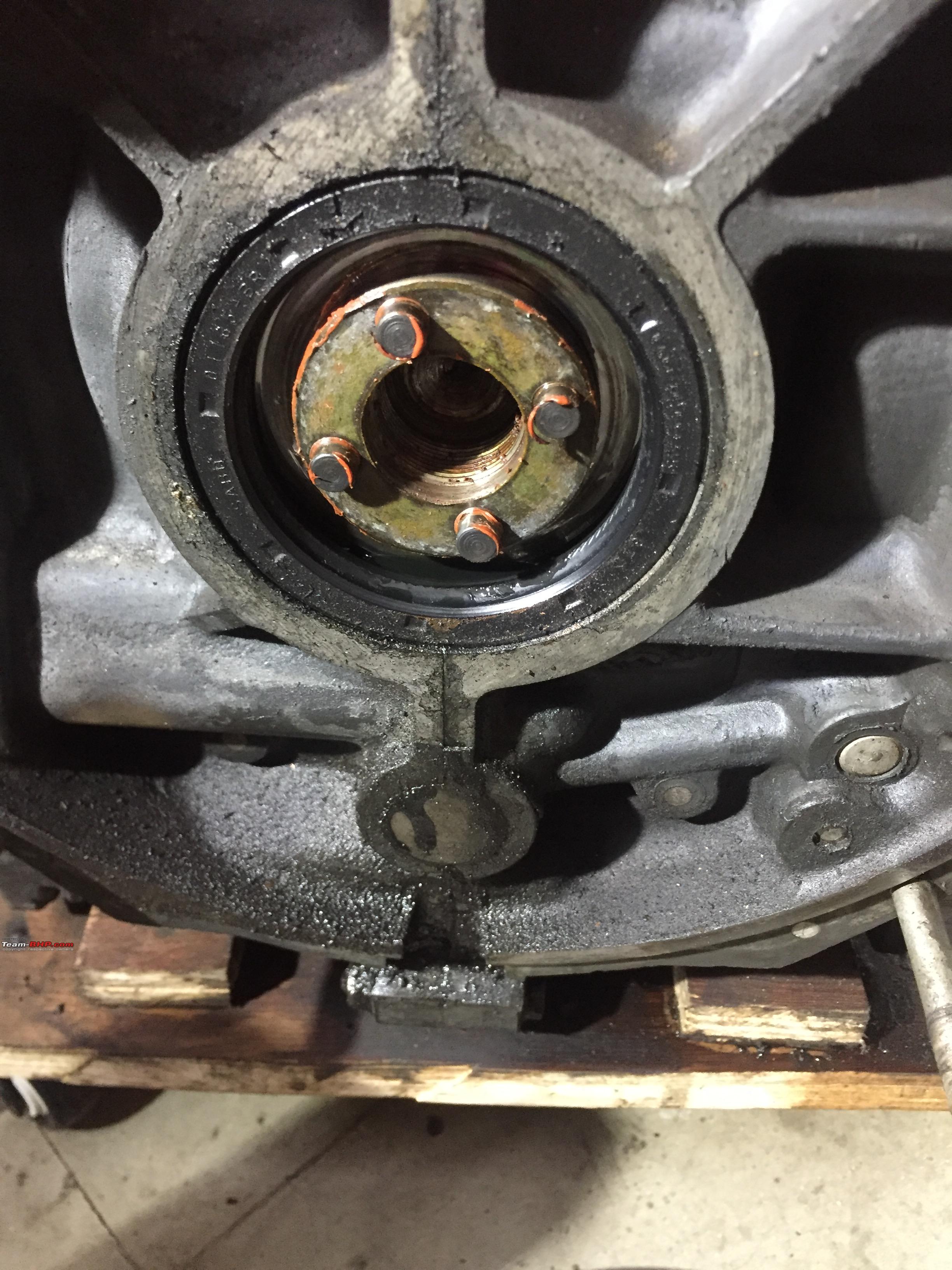
Then I reinstalled the bearing, the spacer, the turn signal switch.

Originally I had started with the intention of solving a slight play in the steering wheel. I had hoped the new spacer would solve that. It did not. The play was due to a worn steering column bearing.

Im going to try to see if I can find a suitable bearing here. Its a single row deep grove ball bearing 24mm ID x 40mm OD x 8mm thickness. Im hoping one of the members on this forum can help me locate a replacement.
I finally had everything back together and was pleased that this time there were no shocking (pun intended!) surprises. I measured about 1V improvement in the voltage drop and the dash lights were noticeably brighter. Even the horn issue was fixed.
In many of the DIY repairs I undertake, Ive often experienced that the repair gets worse/more complicated than I originally estimated. But, sticking it out has almost always paid off.
Cheers!
Byas


 12th April 2015, 12:28

 (3)
Thanks
(3)
Thanks