Coding changes/Adaptations for the Highline RVC to work: Under module 19 CAN Gateway:
Enter secure access code 20103
19 - adaptation → Installation list - specified installations - Camera System Rear View →
coded Under module 5F Infotainment:
5F → adaptation → Car Function List BAP Gen2 VPS_0x0B → activated
5F → adaptation → Car Function List BAP Gen2 VPS_0x0B_msg_bus → Comfort data bus
For cars already having RVC low installed, the infotainment needs to know this is no longer active, else it will get confused
5F → adaptation → function configuration rvc-rear view low_rvc → not activated
Under module 10 Park/Steer Assist(Only if applicable)
10 - Long Coding - Byte: 02 → Bit: 4 → enable (camera installed)
Under module 6C Back-up cam
This module has to be detected by the diagnostic tool if the installation is correct. It need not be coded into gateway to see this new module. If its not present, then either the camera is not powered on or not connected correctly via CAN.
Also it must be noted that most cameras from Aliexpress/used parts come pre-coded with most of the parameters. If you use a new camera as an original spare part, it might need fresh coding:
6C → Long Coding - Byte: 10 → Bit 6 BAP for display data
6C → Long Coding → Byte: 00 → vehicle brand
6C → Long Coding → Byte: 01 → vehicle class and generation
6C → Long Coding → Byte: 02 → vehicle body type
6C → Long Coding → Byte: 03 → region
6C → Long Coding → Byte: 04 → Bit 1 Optical Parking Sensors (OPS) installed(if installed)
6C → Long Coding → Byte: 04 → Bit 2 ParkSteer Assist (PLA) installed
6C → Long Coding → Byte: 04 → Bit 5 DSG/Automatic Transmission installed(if applicable)
6C → Long Coding → Byte: 10 → Bit 5 Rollback recognition(Havent really figured this out)
6C → Long Coding → Byte: 07 → Bit: 0 → enable (standard 90į view)
6C → Long Coding → Byte: 07 → Bit: 1 → enable (parallel parking assist view)
6C → Long Coding → Byte: 07 → Bit: 2 → enable (towing view)
6C → Long Coding → Byte: 07 → Bit: 4 → enable (fish-eye/cross-traffic view)
6C → Long Coding → Byte: 08 → Bit: 2 → enable (manoeuvre light)
After this, clear any errors in various control modules. The Gateway will have a DTC if you code the camera in before connecting it, or vice versa both ways which can be cleared. The camera will have DTCs related to basic setting not done. Apart from this, other DTCs should not be present.
However, even at this point, there will not be any video feed from the camera BUT there will definitely be a black screen like shown above. The calibration process is something that will need ODIS(some people online mention its possible through OBD11 but I am not sure) you will have to coax someone with ODIS(like an FNG or if you can really do it with ASC

).
Calibration of the RVC:
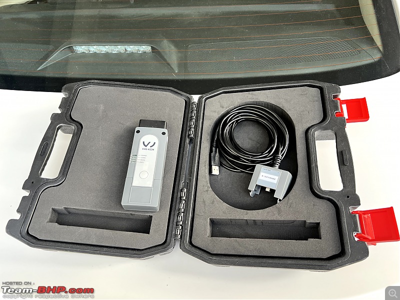
The diagnostic interface through which ODIS which has a guided function for calibration will run:

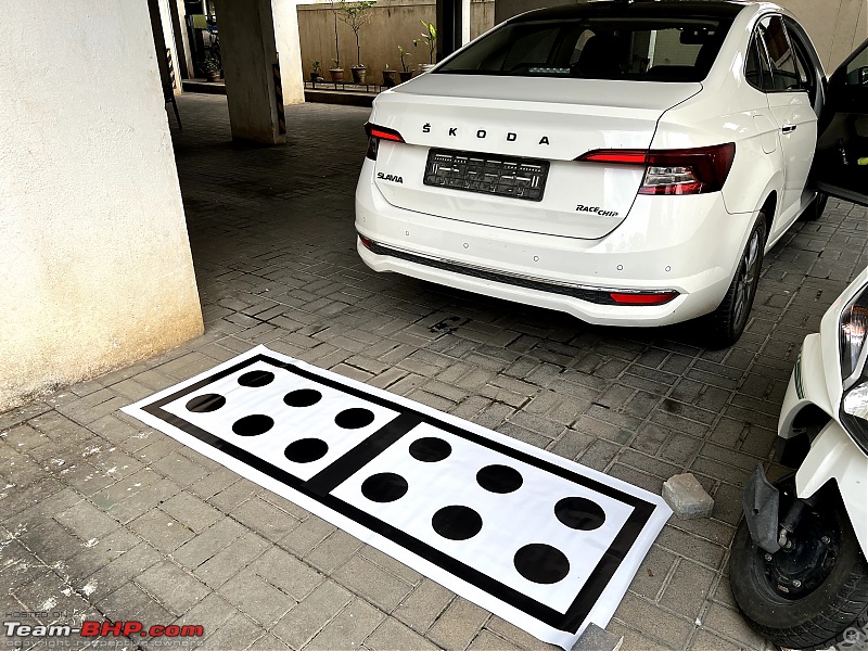
Also, another important thing is that the calibration process needs a target board or a mat with a pre-defined pattern. This is mandatory else the process will fail. The mat has dots and a frame which is used by the camera to cut out the reverse video feed in the right perspective. Else the camera image will look wierd. The camera has a high resolution image feed out of which the various views will be cut out by the control module and for this, the results of the calibration has a direct bearing.
I got the calibration mat printed nearby at a printer on a flex vinyl for a meager 400 rupees and that did the job perfectly

.

- The car must be on a dead flat surface and in a brightly lit area
- There should be no shadow of the car falling on the mat
- The mat should be placed centered to the car and roughly around 1.5m from the rear axle of the car
- The car steering should be straight and there should be no load in the car
The calibration process is started in ODIS by selecting the control module 6C Reverse Camera and under guided functions, we select camera calibration. The process is demonstrated in the video which follows.
Once the process begins or before it, there are two main measurements necessary. One is the
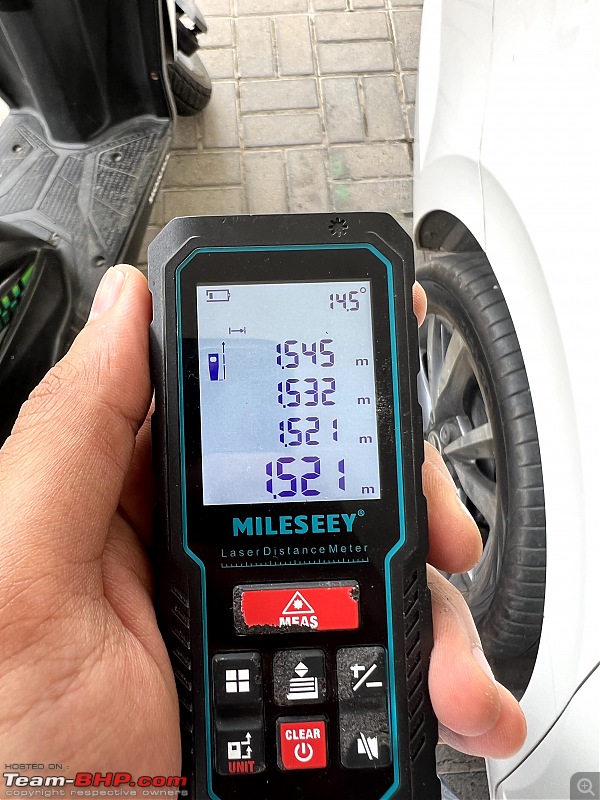
distance from the center of the rear axle to the start of the calibration board. This should be measured on both sides, preferably with a laser measuring device or even a tape will work.

I adjusted the mat to get both readings accurate, or at least nearly equal since its in milimeters. You can see those values in the history of the device. But I would assume a 0.5cm accuracy limit should be sufficient.
The second measurement is the
height of the camera from the ground. This is again something which is quite sensitive. For my car its 900mm roughly

The third measurement that the process will need is the
height of the calibration board from the ground. The official VW tool uses a foldable board which has a certain thickness. Since I used a mat which is close to nothing, I entered a small value. The calibration process takes around 20 seconds after this step and after this, the reverse camera image is displayed. Here is a video demonstrating the process:
Voila, after this the reverse camera started working. The camera output is far better than what came as stock. However, there was one issue, the mat was slightly offset in the first try and I had not got the measurements to the best accuracy:

You can see that the image is slightly rotated and is not straight by the reference marks I have made
 After recalibrating the camera:
The regular reverse view

The parallel park mode which I will explain separately

The towing assist mode which helps for closing in against a wall or so

Will update detailed demo of the camera in the subsequent post. Stay tuned.

 (28)
Thanks

 (17)
Thanks

 (16)
Thanks

 (29)
Thanks

 (58)
Thanks
 (3)
Thanks

 (1)
Thanks
 (4)
Thanks

 (2)
Thanks
 (1)
Thanks

 (2)
Thanks

 (2)
Thanks


 .
. 


 .
.