Team-BHP > Technical Stuff > DIY - Do it yourself
Register New Topics New Posts Top Thanked Team-BHP FAQ


Reply
  Search this Thread
59,225 views
Old 28th June 2007, 10:21   #1
BHPian
 
archat68's Avatar
 
Join Date: Dec 2006
Location: Kolkata
Posts: 905
Thanked: 642 Times
DIY - Microcontroller based digital tachometer

Hi,
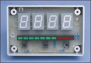
I've been looking for a tachometer for for my 2000 Zen. I learnt that good ones with shift light cost u around 2.5K. So I dived into DIY. After searching the net I decided to build the tachometer published in Siliconchip April 2000. Its designed around a PIC microcontroller and very sophisticated. You can set for work from 2 to 12 cylinder engines. Beside a digital readout you also gets a LED bargraph display which u can use as a shift light indicator. Here is the picture from the magazine:

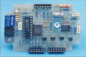
I started with fabricating the board from plain copper clad PCB, which is the toughest part of it. After that I programmed the microcontroller with the source source code which is already available at the Siliconchip site fitted and soldered all components on the board and voila.


Its the picture of the tacho built by myself at the testing stageand tested with a 3V AC signal at the input stage and no. of cylinder set to 2. MAins AC is 50 Hz or 3000 rpm by setting the cylinder no. to 2 it gets divided by 2 by the tacho and hence the display is 1500. also note three leds glowing - each led here correspond to 500 rpm. i've set 2500 as the shift point and fitted a blue led at the 5 th led when it lights i shifts. Also the redline limit has been set to 4000, so when 4000 reches the last 3 red leds glow. However u can set the redline limit to anything between 1000 to 9900 by the three switches on the front panel. already installed in the car for more than 2 month - but looking for a decent cabinet - suggestion anyone?
Here it goes:


The lower one is a battery monitor built by me - it indicates voltage from 12.5 to 15V with the help of a series of red - green and yellow led.
The tacho costed me 200 bucks - thanks to free sample of microcontroller and LED display given by Microchip and BIvar ( manufacturer of these components) and DIY. But should not cost more than a 1000 bucks (maximum) if all the components are purchased from the market.

So long live D-I-Y

________
Arup
archat68 is offline   (1) Thanks
Old 28th June 2007, 10:49   #2
Team-BHP Support
 
tsk1979's Avatar
 
Join Date: Feb 2005
Location: San Jose, CA
Posts: 23,695
Thanked: 23,484 Times

All I can say is "Wow" great job.
Thats a neat little gadget you made.
But Zen is a 3 cylinder car, right?

And what is the principle behind this. i.e. where does this get the input voltage from?
I am assuming it works by measuring the residual AC in the DC voltage or something?
More details please
tsk1979 is offline  
Old 28th June 2007, 11:00   #3
BHPian
 
Join Date: Jun 2007
Location: Mumbai
Posts: 90
Thanked: 0 Times

that sure is a 'WOW'.
give in more details and the accuracy details on a prefitted tacho car.
great going bro !
mainak is offline  
Old 28th June 2007, 11:08   #4
Senior - BHPian
 
VJ_MAVRICK's Avatar
 
Join Date: Jun 2007
Location: Sydney
Posts: 1,239
Thanked: 34 Times

Great work Archat and do let me know once you get the cabinet fixed and get it working in full blow ..might decide to buy from you itself ...cheers bro
VJ_MAVRICK is offline  
Old 28th June 2007, 11:13   #5
Senior - BHPian
 
abhibh's Avatar
 
Join Date: Sep 2005
Location: Back in the HOOD near you!
Posts: 2,768
Thanked: 39 Times

WOW dude awesome. I am sure as soon as MANIK see's this thread you gonna get a loads of PM's ...

BTW can you also post installation pics if you have taken them ?
abhibh is offline  
Old 28th June 2007, 11:16   #6
SRK
Senior - BHPian
 
SRK's Avatar
 
Join Date: Sep 2005
Location: Mumbai
Posts: 1,206
Thanked: 536 Times

That thing is really good..
By the way what goes in to connect the whole system to the car?

I mean any modifications required?
SRK is offline  
Old 28th June 2007, 11:26   #7
Senior - BHPian
 
Join Date: Mar 2006
Location: Faridabad
Posts: 6,813
Thanked: 306 Times

Quote:
Originally Posted by tsk1979 View Post
All I can say is "Wow" great job.
Thats a neat little gadget you made.
But Zen is a 3 cylinder car, right?

And what is the principle behind this. i.e. where does this get the input voltage from?
I am assuming it works by measuring the residual AC in the DC voltage or something?
More details please
It is taken from the spark plug sir. and the zen is a 4 cyl car.

And archat from where did you got the electronics stuff any address or web link.
low_bass_makker is offline  
Old 28th June 2007, 11:31   #8
BHPian
 
rishibravo's Avatar
 
Join Date: Jul 2006
Location: New Delhi
Posts: 579
Thanked: 12 Times

wow really cool gizmo you made maan. Whats the funda behind it. Can we get a link or something .
rishibravo is offline  
Old 28th June 2007, 12:35   #9
Team-BHP Support
 
moralfibre's Avatar
 
Join Date: Dec 2004
Location: MH-12
Posts: 8,560
Thanked: 14,440 Times

archat68, nice work and excellent DIY effort.
moralfibre is offline  
Old 28th June 2007, 12:43   #10
Senior - BHPian
 
BUSA's Avatar
 
Join Date: Aug 2005
Location: Bombay
Posts: 5,127
Thanked: 23 Times

Excellent work there Arup
BUSA is offline  
Old 28th June 2007, 12:55   #11
BHPian
 
archat68's Avatar
 
Join Date: Dec 2006
Location: Kolkata
Posts: 905
Thanked: 642 Times

Thanks guys.
Zen is 4 cylinder. You get the input from either low voltage input at the ignition coil or from your ECU (it connects where a normal tacho connects in a car).
Here is the link for another forum where it was posted on my request:
Electronics Lab - Community

The circuit is pretty accurate. As u can see on the testing stage u get a reading of 1500 for a 1500 rpm signal fed to the input. The only con is the display increment is of 100 rm. So for rpm below 750 (say) u get 700 and for rpm above 750 u get 800 on the display.

The circuit has other feature like revv limiter output (if u have one).
So enjoy and if anybody needs any help - let me know.
_________
Arup

Last edited by archat68 : 28th June 2007 at 13:04.
archat68 is offline  
Old 28th June 2007, 20:25   #12
Team-BHP Support
 
CrAzY dRiVeR's Avatar
 
Join Date: Jun 2006
Location: Bangalore / TVM
Posts: 18,006
Thanked: 78,833 Times

WOW!

Again... but cant help it. Nice work! better pics would surely do justice to the work.
CrAzY dRiVeR is offline  
Old 28th June 2007, 23:00   #13
Senior - BHPian
 
manikjeet's Avatar
 
Join Date: Sep 2006
Location: chandigarh
Posts: 1,617
Thanked: 296 Times

wooo man that a great DIY and its my next DIY great work man

and pointer you would like to give out before i try to make it
manikjeet is offline  
Old 28th June 2007, 23:36   #14
Distinguished - BHPian
 
theMAG's Avatar
 
Join Date: May 2006
Location: Avon, CT
Posts: 7,196
Thanked: 1,821 Times

Great job, archat68. This is where Indians shine - resourcefulness
theMAG is offline  
Old 28th June 2007, 23:37   #15
Senior - BHPian
 
Join Date: Mar 2006
Location: Faridabad
Posts: 6,813
Thanked: 306 Times

Quote:
Originally Posted by archat68 View Post
The only con is the display increment is of 100 rm. So for rpm below 750 (say) u get 700 and for rpm above 750 u get 800 on the display.
this is a minor thing but the project overall is quite nice..
low_bass_makker is offline  
Reply

Most Viewed


Copyright ©2000 - 2025, Team-BHP.com
Proudly powered by E2E Networks