| |||||||

 |
| Search this Thread |  30,593 views |
 26th December 2019, 11:28
| #1 |
| Distinguished - BHPian  | DIY - Maruti Alto K10 - HID Fog Light Installation 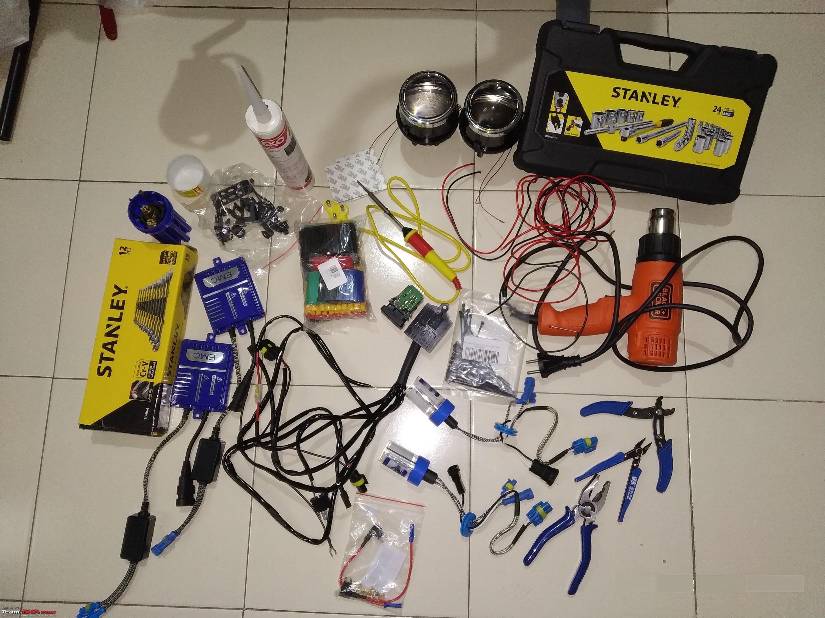 The Suzuki AltoK10 is my city run about. Office runs, occasional social visits & shopping cart. The car's H4 halogen headlamps are really poor (like any other stock setup on sale on this side of 15 lakh rupees!) The car is a VXi (Opt) AGS trim. So while VXi, the car lacks body coloured handles & front fog lights. The inadequate headlamps mean front visibility even in city confines is very poor in rains and in general. The car really needs extra lighting & increasing bulb wattage has never been my preference with any car. Installing fog lights was the only option always. Recently I installed HID projector fog lights in my primary car. And that was insanely easy as a DIY. Considering the negligible (relative to the extra safety & light on offer) price difference in OEM halogen fog lights & HID projectors, it was a no brainer decision & I decided to install the HID fog lights as a DIY again with this car. Since I had already done this on the primary car - I had already learnt a few things the hard way. The wiring connections, planning for switching mechanism is cleaner & better planned in this car. The project also took half the time than the Nexon since I didn't commit any silly mistakes like installing the projectors upside down! Technically - the installation in Nexon is actually far easier. The Nexon has much cleaner setup & very good accessibility all over the engine bay. Design is better & easier to work with. In the Alto - there is no alternative but to fully remove the bumper for this project. So do not attempt to do this unless you are ready to go through that at your home. Ordered this kit from MotorBasket, Delhi just like the previous one for Nexon. Due to some error in dispatch, I received a 5500K bulb kit instead of 4300K that I wanted. The MB team immediately offered to replace, however I thought of sticking with the 5500K to check it. Since the Alto is purely for city drives & not regular for monsoon night drives, the whiter shade would actually be better perhaps. Worth a try surely. HID Kit contents -
Tip - I suspect 2.5" projectors might be an easier fit in the housing. I had to cut the bumper in a couple of small places to make these fit. Extras that I used from my own inventory -
Also ordered an OEM fog light switch from boodmo for a clean install. Sourced from here - Link - Boodmo - MSIL OEM FR FOG Switch We'll complete this DIY in the following parts -
TIP - This DIY process will work with little modifications with a lot of cars. Especially Marutis. Concept will remain the same for any car. Wiring routing & mounting will defer, that's all. A usual weekend at Reinhard's Lair -   Last edited by Reinhard : 30th December 2019 at 16:09. |

|  (24)
Thanks (24)
Thanks
 |
| The following 24 BHPians Thank Reinhard for this useful post: | 2himanshu, Ashtoncastelino, COMMUTER, dailydriver, digitalnirvana, Geo_Ipe, GTO, hemanth.anand, hmansari, InControl, jailbird_fynix, Leoshashi, Researcher, Romeo_Mike, self_driven, Simat, SmartCat, smuniswami, THE_DRIFTER, TROOPER, vaasu, vaish9925, VinodDevil81, yesyeswe |
| |
|
27th December 2019, 13:32
| #2 |
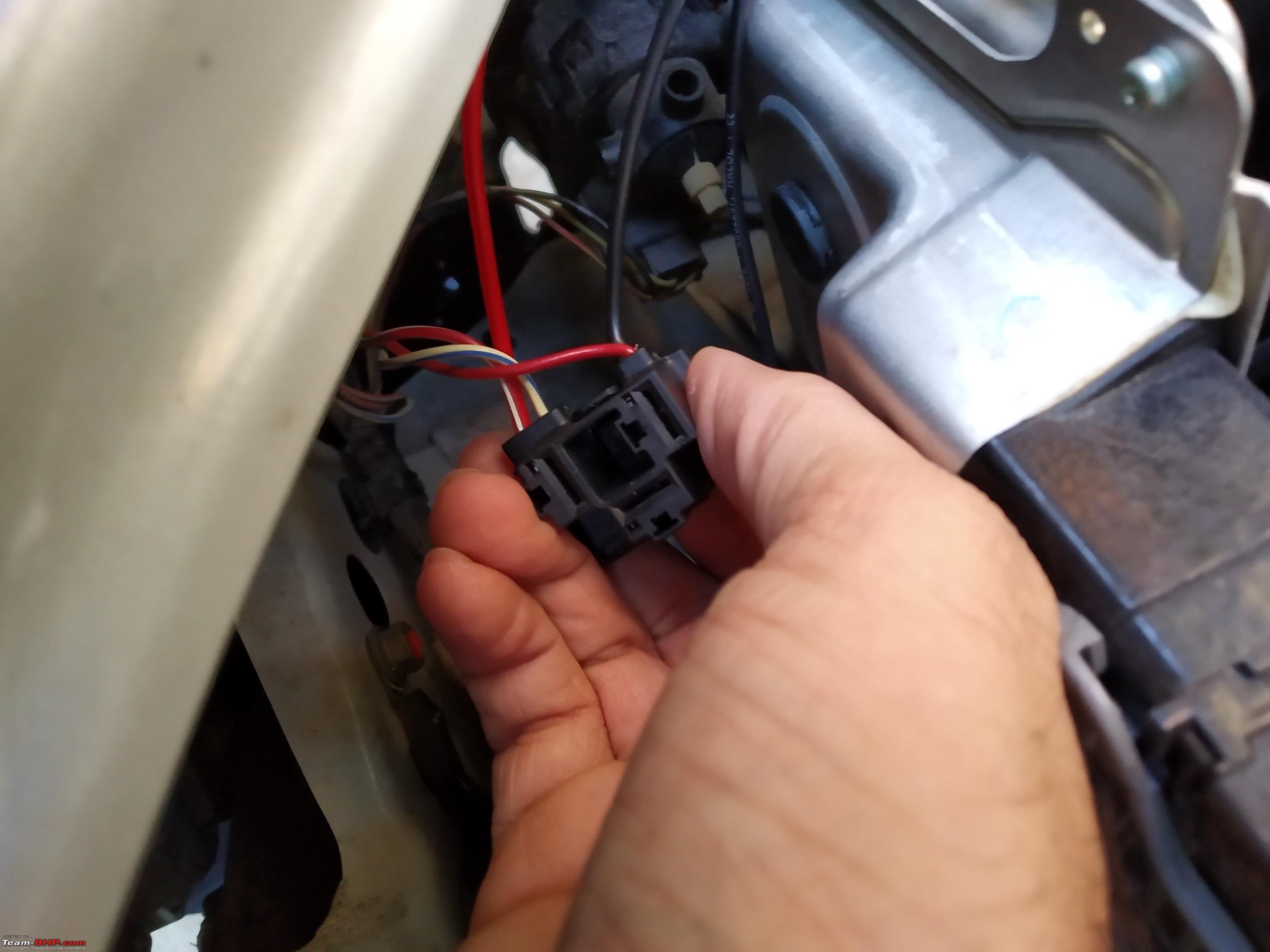
| Distinguished - BHPian | re: DIY - Maruti Alto K10 - HID Fog Light Installation Step 1 - Preparing the wiring harness & switch Like mentioned above, I ordered a heavy duty H4 connector triggered harness along with the kit. About the harness. This harness has -
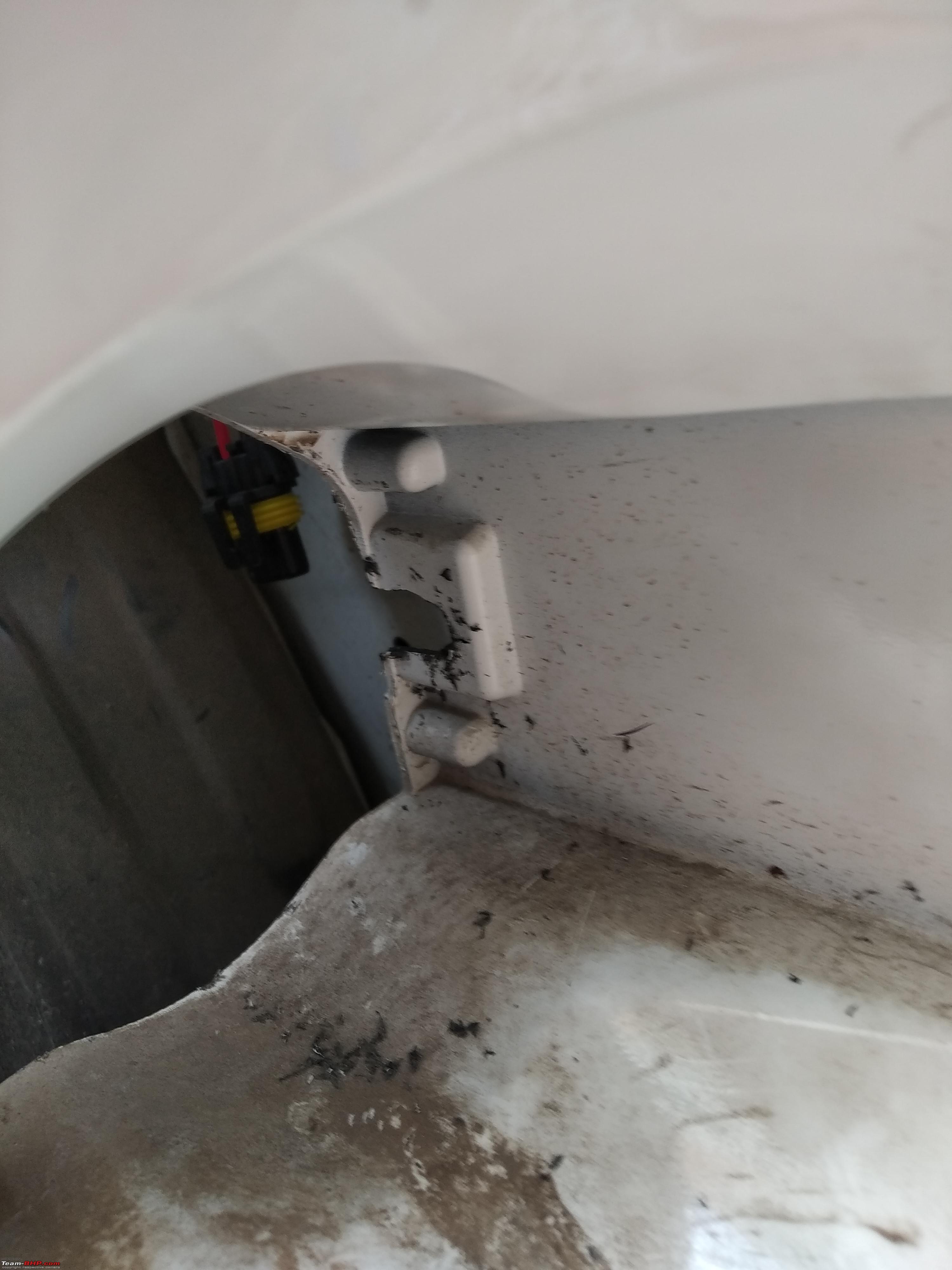
The wiring for the solenoid actuators isn't done too smart & is actually hooked up to the ballast powering wires. When using the harness as it is by tapping into stock high beam wire - if you flash high beam, it powers the solenoids as well as the HID bulbs for just a second. And frequently depending on use. Something we totally want to avoid for the health of the ballasts as well as the bulbs. So - I used the connectors from it for solenoids & the ground wire as it is. But I cut away the power wire from it, and hooked it up separately altogether with the stock high beam pin in the headlamp. This way - when I just flash high-beam, only the solenoid trips but fog light bulbs do NOT turn on unless their switch is ON already. [[This tripped me off much later in the installation thanks to a negative switch control for headlamps in the car. If you are doing this in a similar Maruti - Please simply connect BOTH - the read & black wires from the solenoid directly into the 2 respective high beam & ground pins of the stock H4 connector. I learnt this after I had put everything back together & reinstalled the bumper. So instead of removing everything again - I used another small relay to work around this problem. More on that later!]] This is how the harness looks after my modifications. H4 socket removed. positive wire of both side solenoid wires connected using an external red wire. 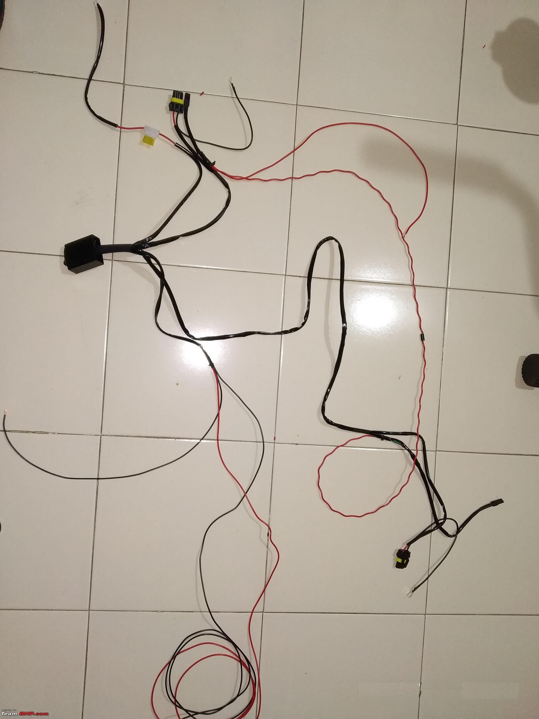 For a longer lasting & stronger connection, always use shrink tubes over solders & if possible reinforce the connection by adding a zip tag near it. 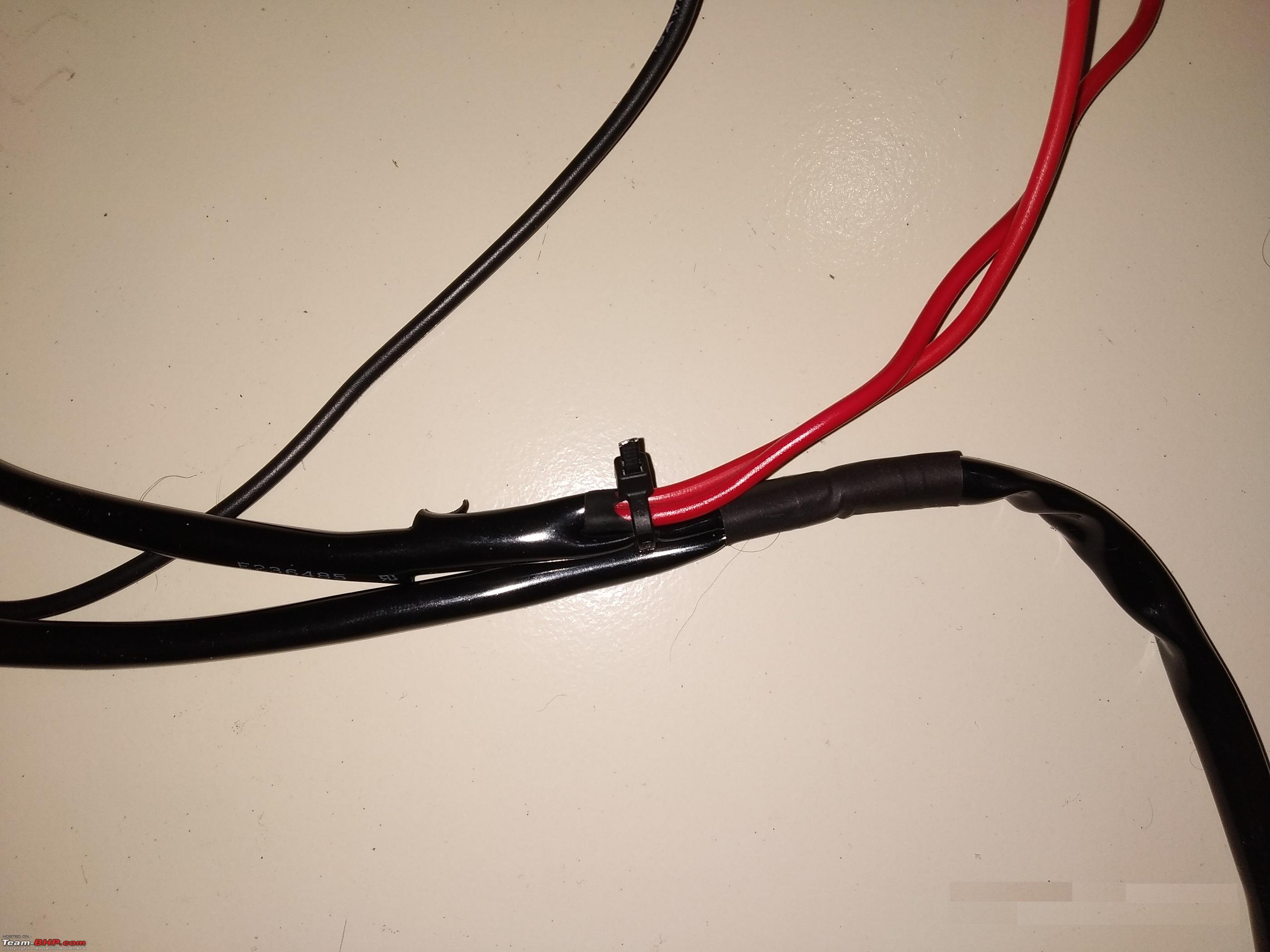 Preparing the fog light switch The switch is for Celerio/Swift/Ertiga etc till recent generations. So it has power inputs for 12V, illumination, illumination brightness etc. I originally planned to take a 12V & ground wire from the engine bay ACC fuse to the switch. However, courtesy @audioholic's Celeriofog light installation thread on this DIY forum, got the tip that I could simply route the wires from the headlamp leveling switch right besides. In the AltoK10, there is no backlight for the leveling switch. Just a 12V input, GND and output for the actuators up front. Simply prop out the leveling button using a screw driver & unhook the plug. Remove the pin using a needle from front. Push in the red and black wires into respective 2 pins in the socket & put the switch back in.  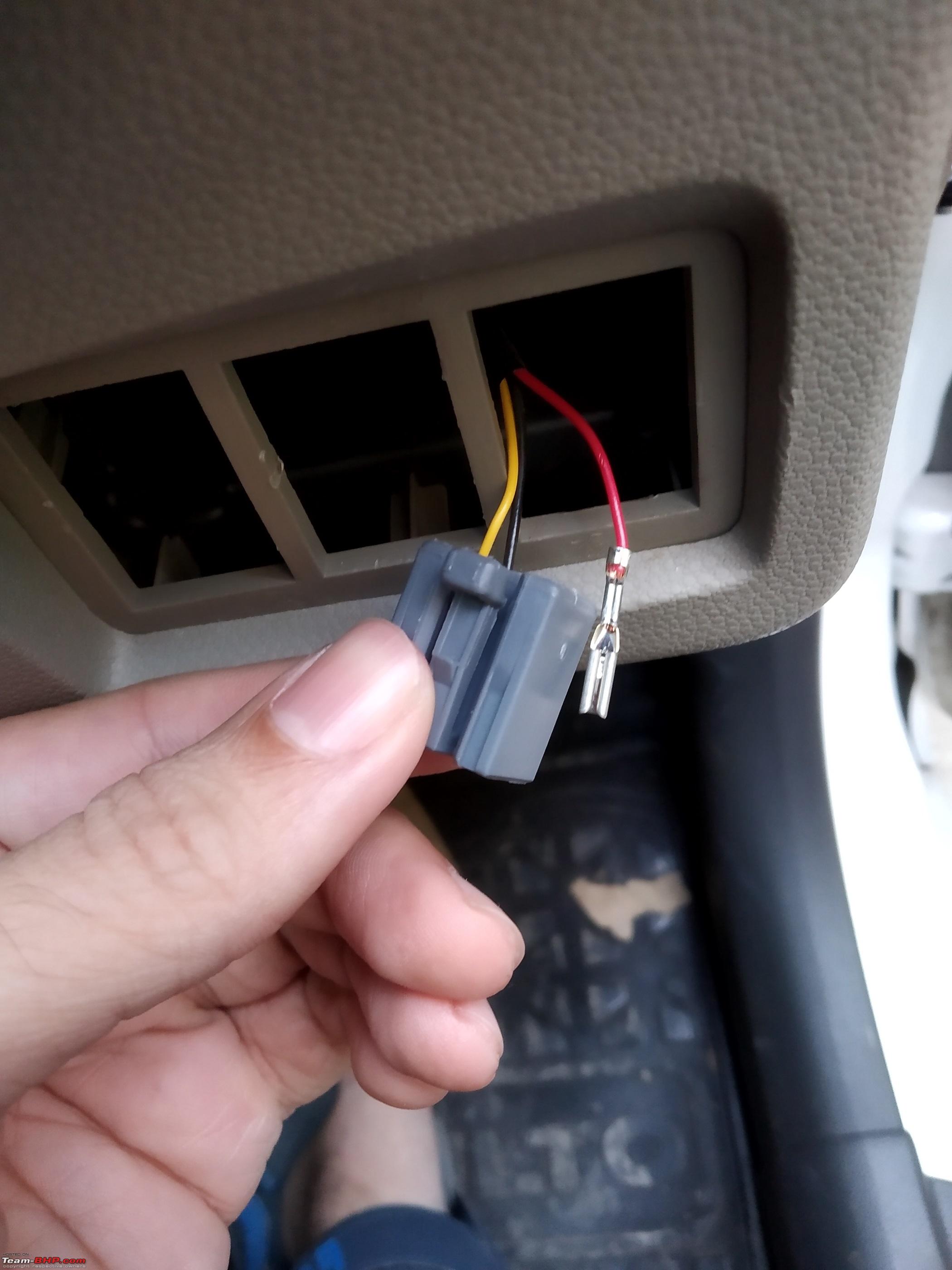 I couldn't find the coupler (G151) to connect to the back side of the OEM fog light switch. (I was lazy to search too much.) So I went a simple crude way & soldered wires to the back of the switch. It has total 5 pins on back. When looking at the pins from back of the switch with the notch on top, do the connections as below -
This is how the finished product should look like. I have also included a shrink tube for better wire management. 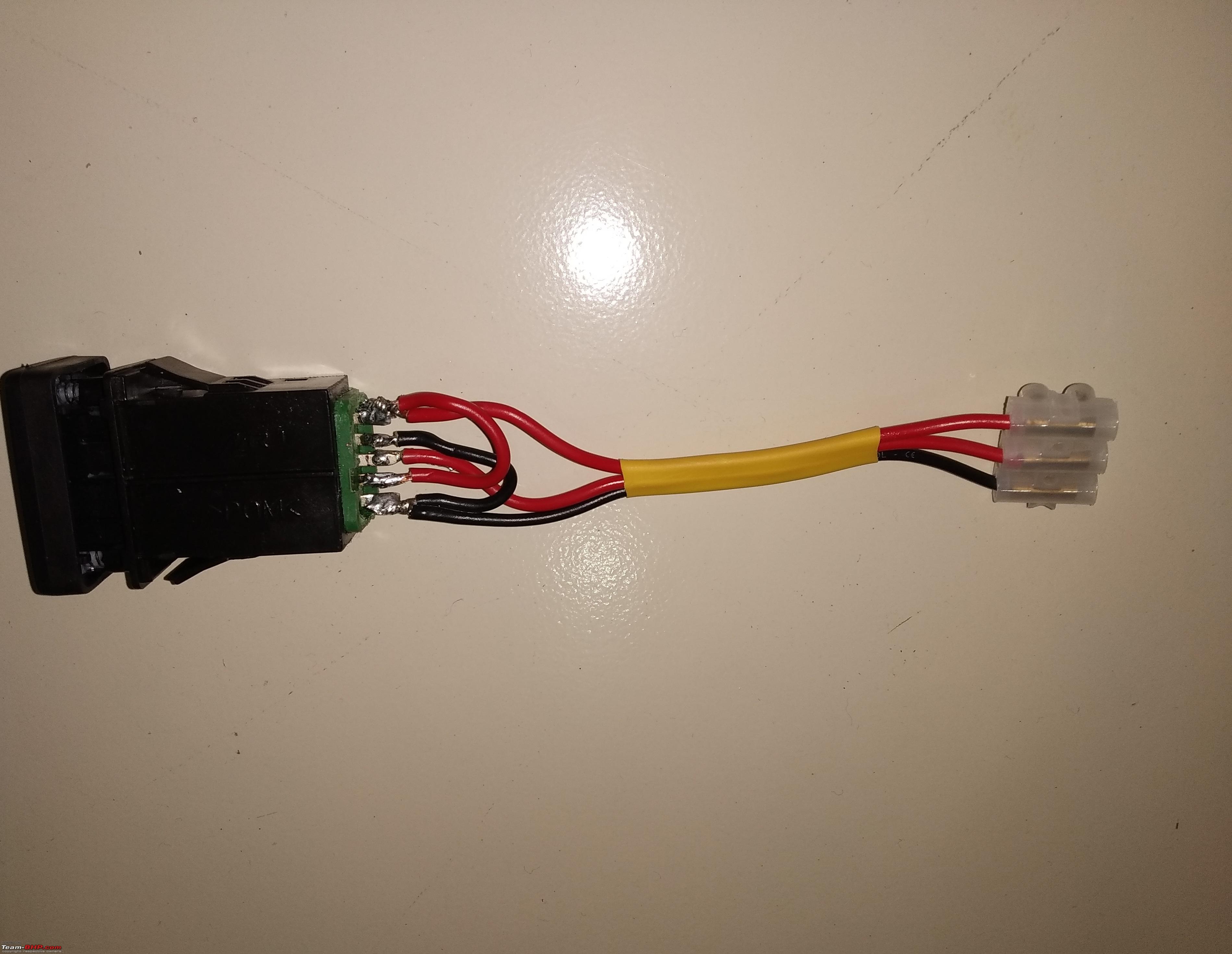 Use the existing firewall grommet's protrusions to make a tiny hole & insert the relay power wire into the cabin. Push it in till you see it lying down into the driver's foot-well. 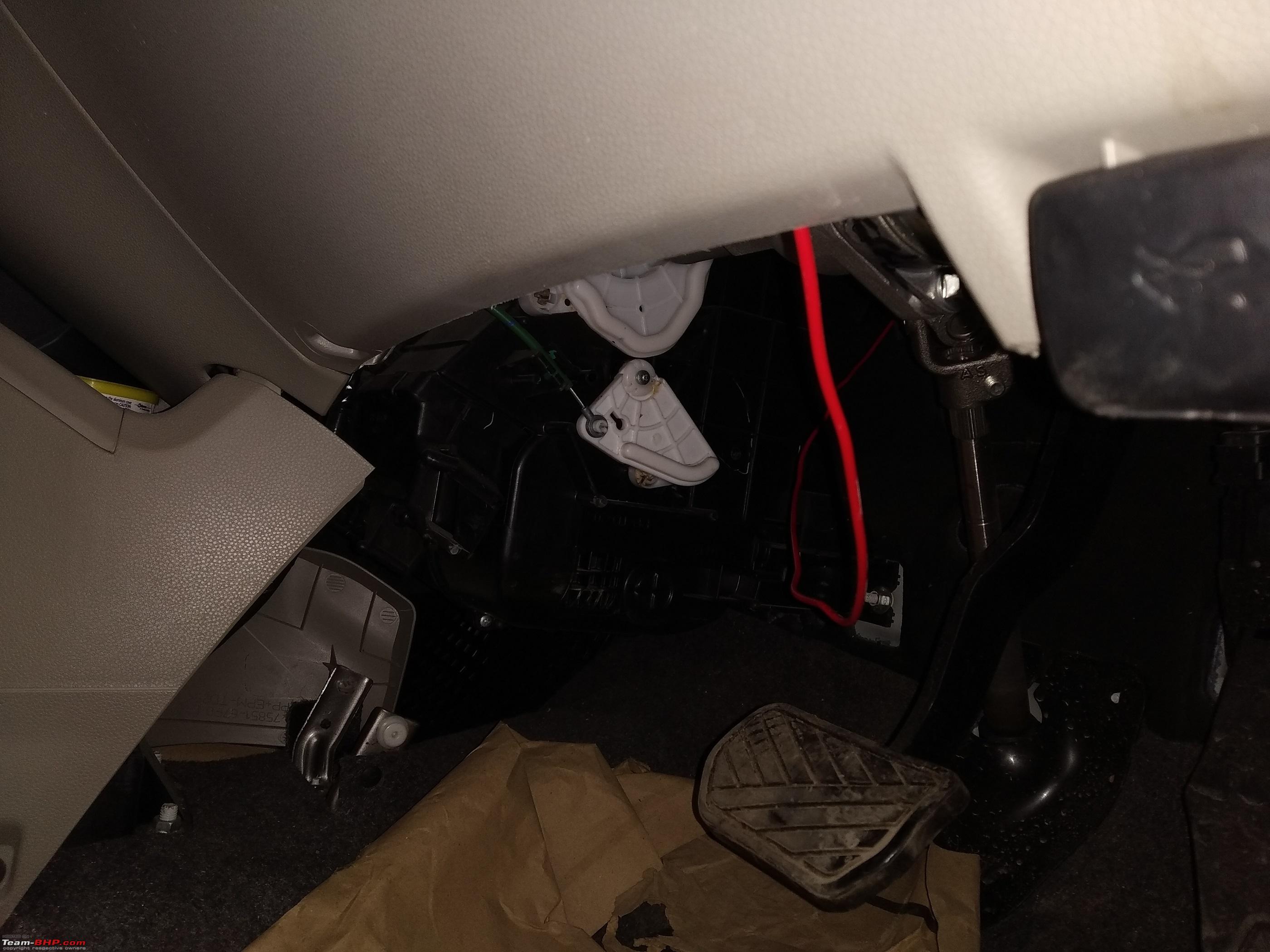 After completing the connections, this is how the final assembly should look like. Push the switch into the slot carefully without getting any wires stuck in the sockets. 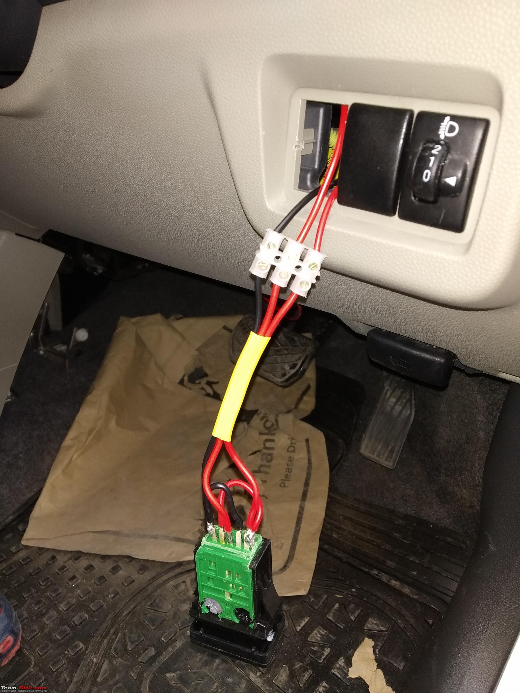 Here's a quick test. The backlight is ON & since the button is pushed in, the green light is also ON. 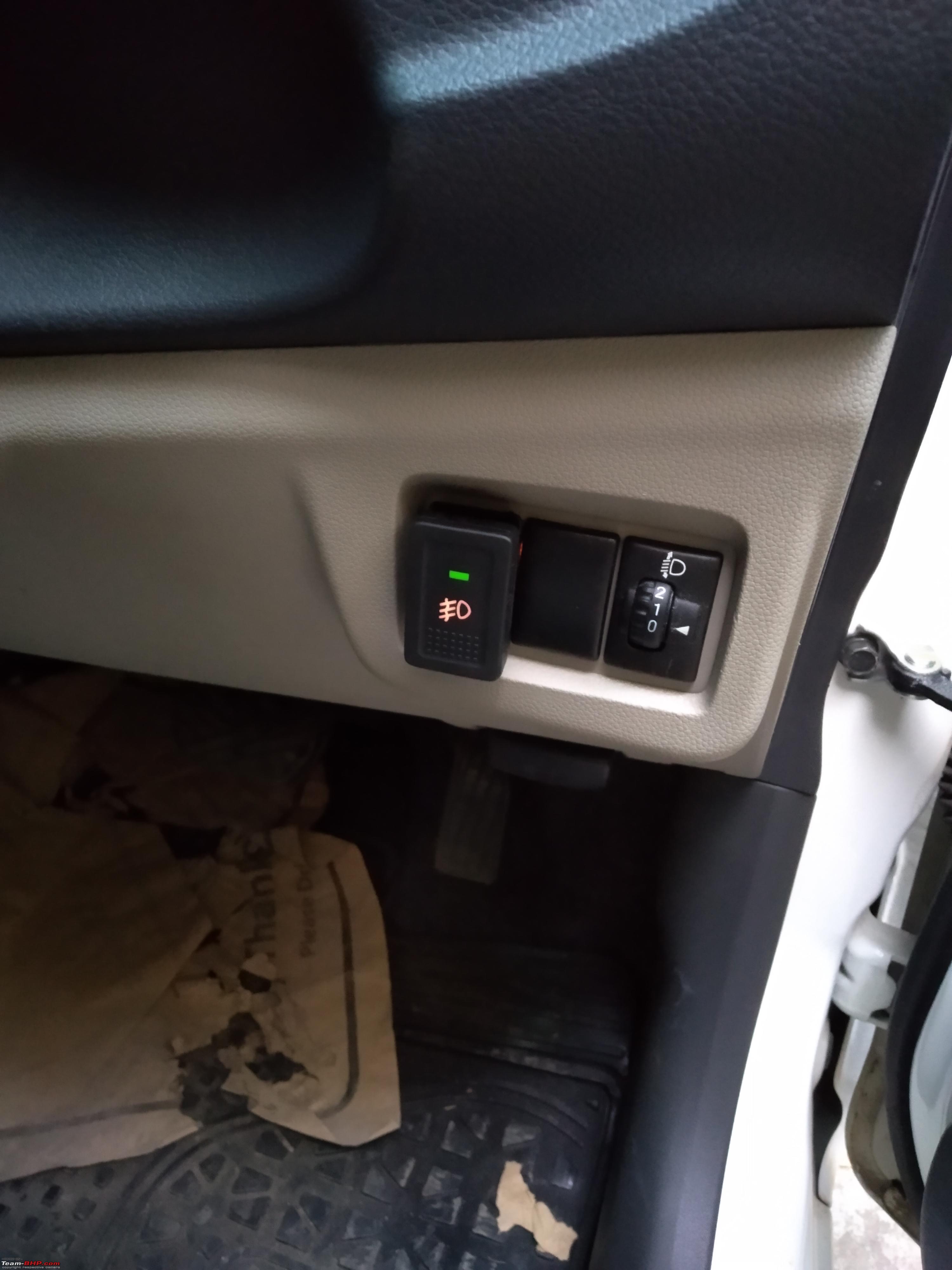 Our work inside the cabin is complete here! Now what remains is the installation of the projectors & completing the wiring. NOTE - We wired this switch for power from the headlamp leveling switch. This switch gets power when the position lamps are turned on. i.e. headlamp stock is turned 1 click forward (or 2 clicks as well). This means the switch we added will function only when at least position lights are turned ON, which is perfect. This means we'll never have a situation where we are using the fog lights but have forgotten to turn on the tail lights while driving in the night. Last edited by Reinhard : 30th December 2019 at 12:52. |
|
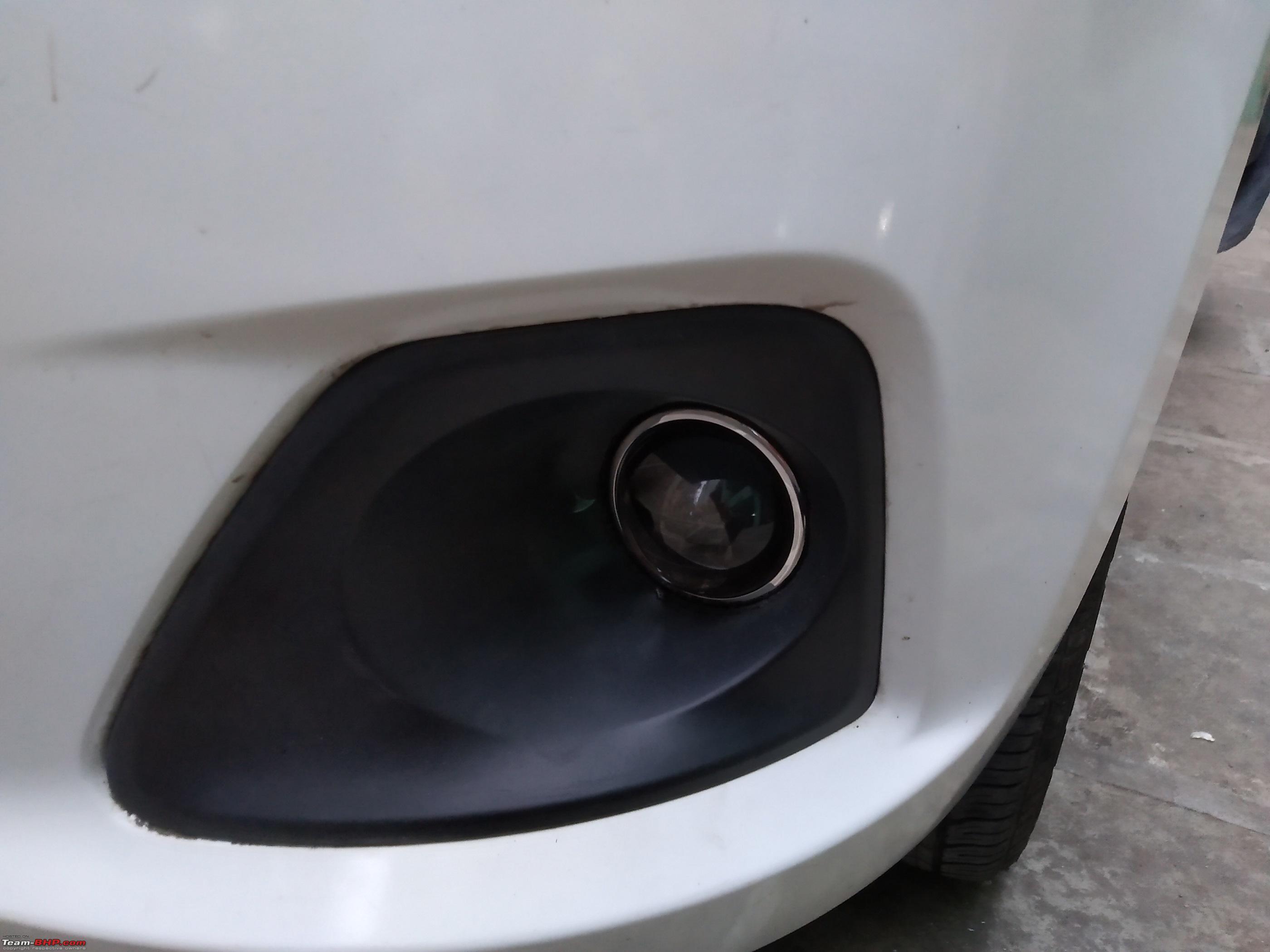
| (17)
Thanks
|
| The following 17 BHPians Thank Reinhard for this useful post: | digitalnirvana, GTO, hemanth.anand, hmansari, InControl, jailbird_fynix, Leoshashi, N33raj, Romeo_Mike, Simat, SmartCat, smuniswami, THE_DRIFTER, TROOPER, vaasu, VinodDevil81, yesyeswe |
|
28th December 2019, 19:44
| #3 |
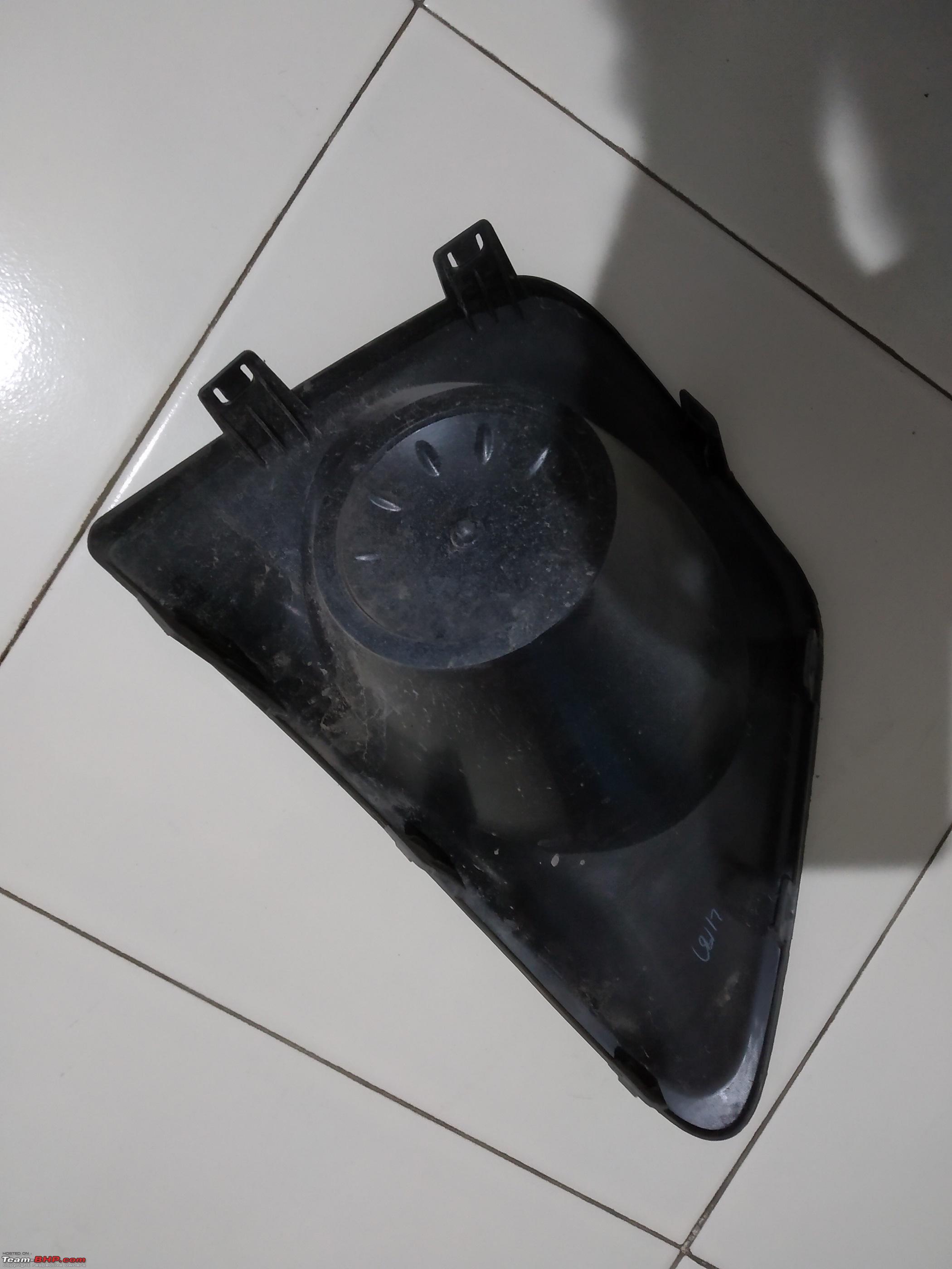
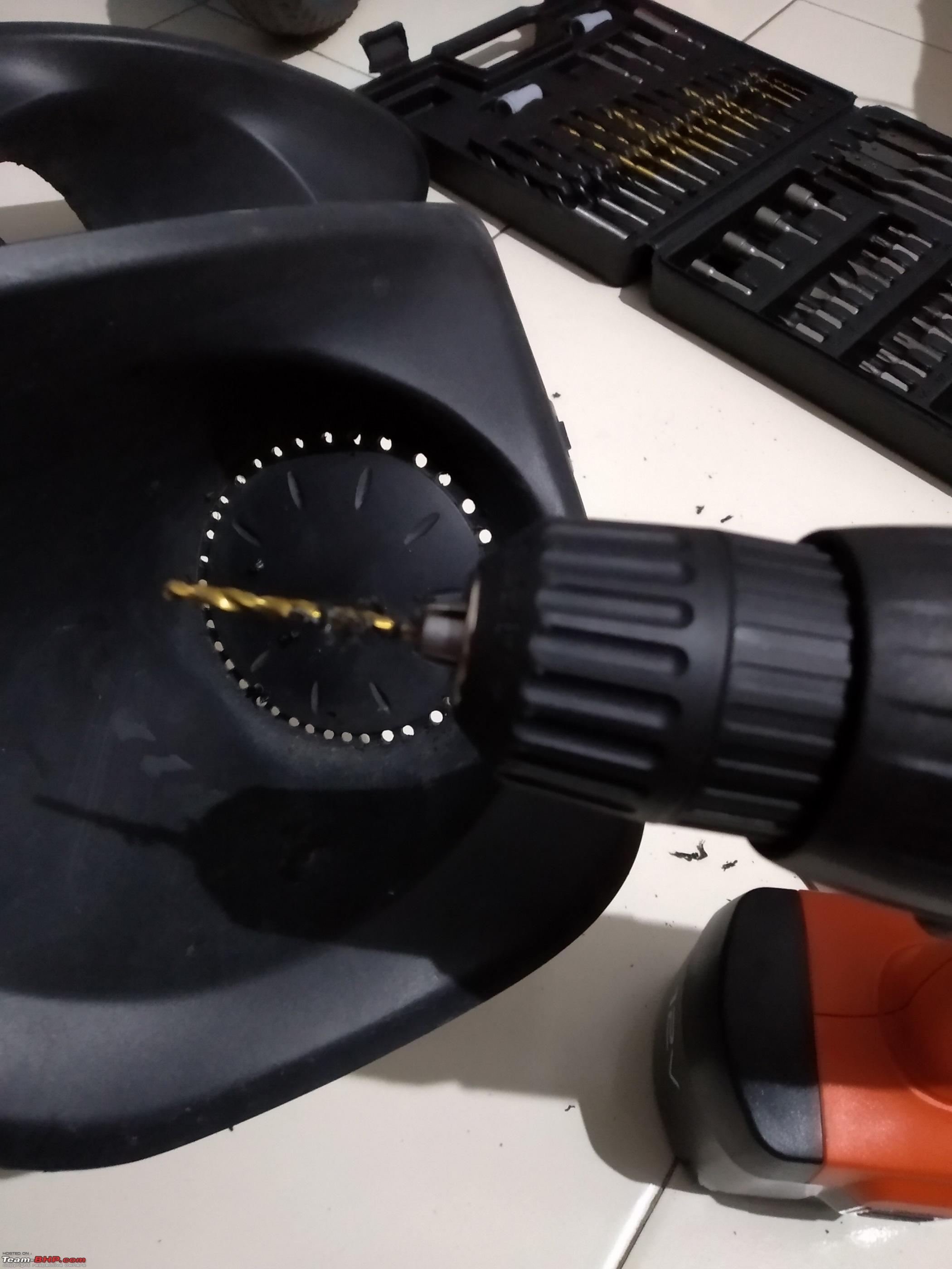
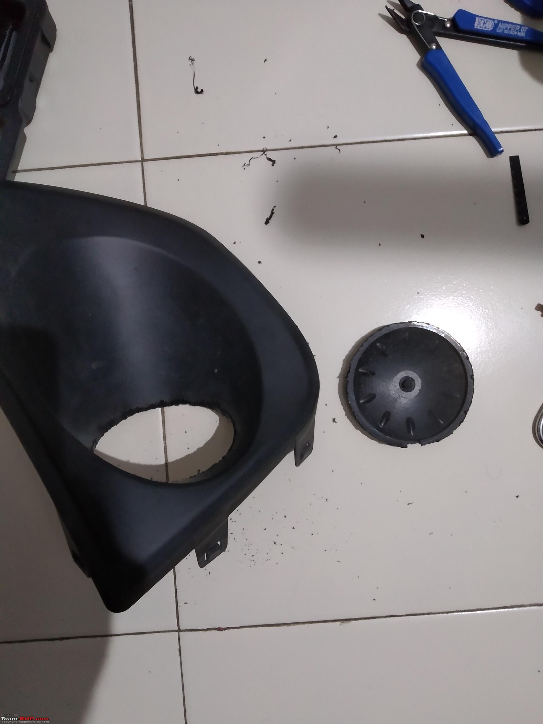
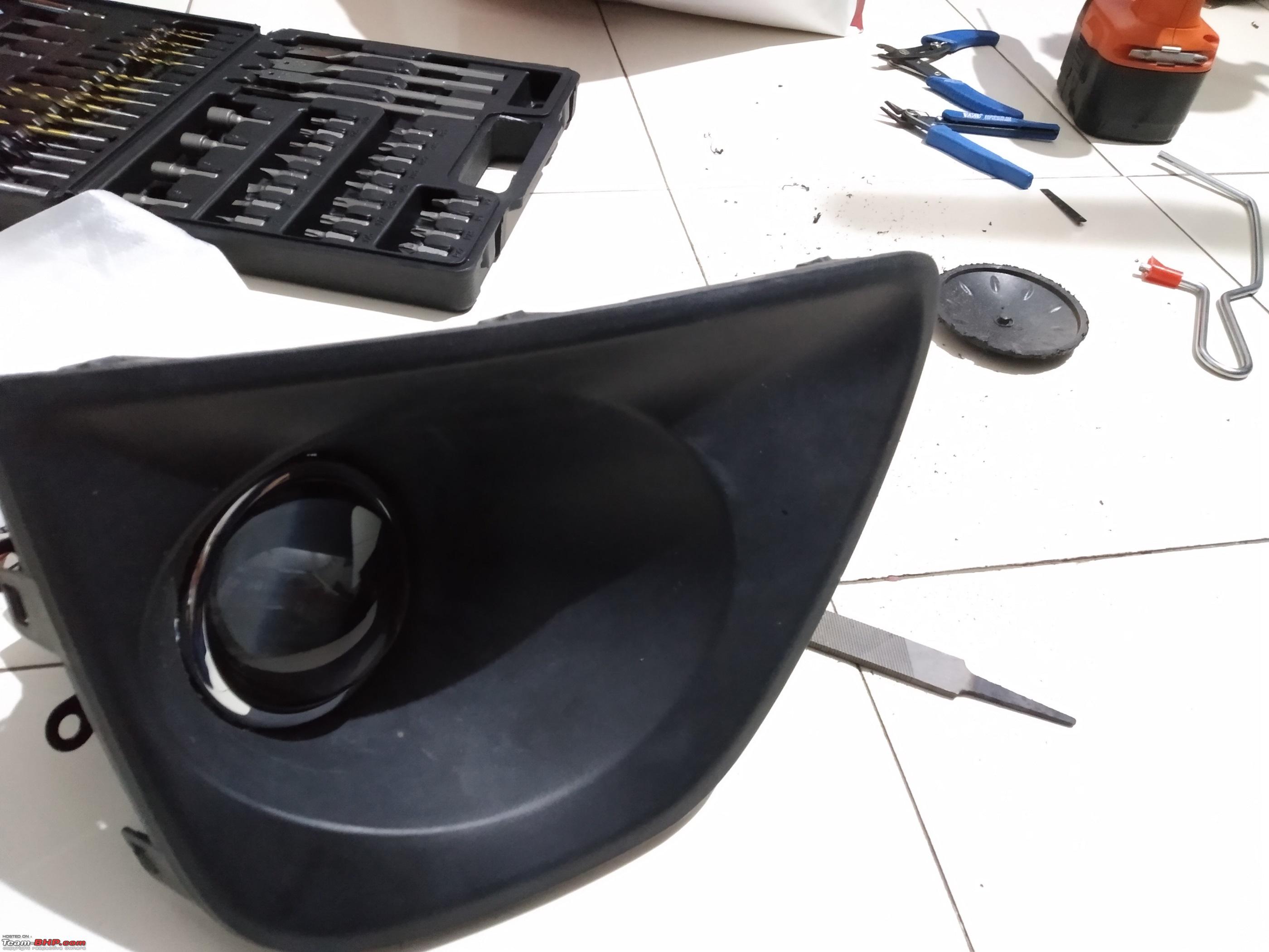
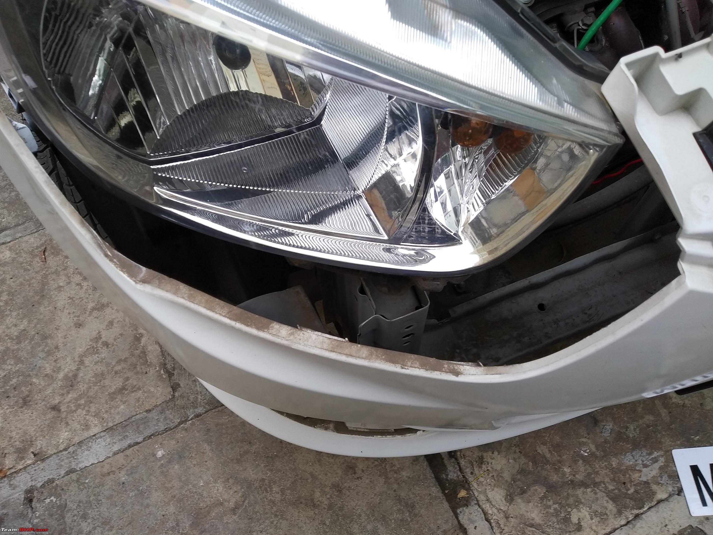
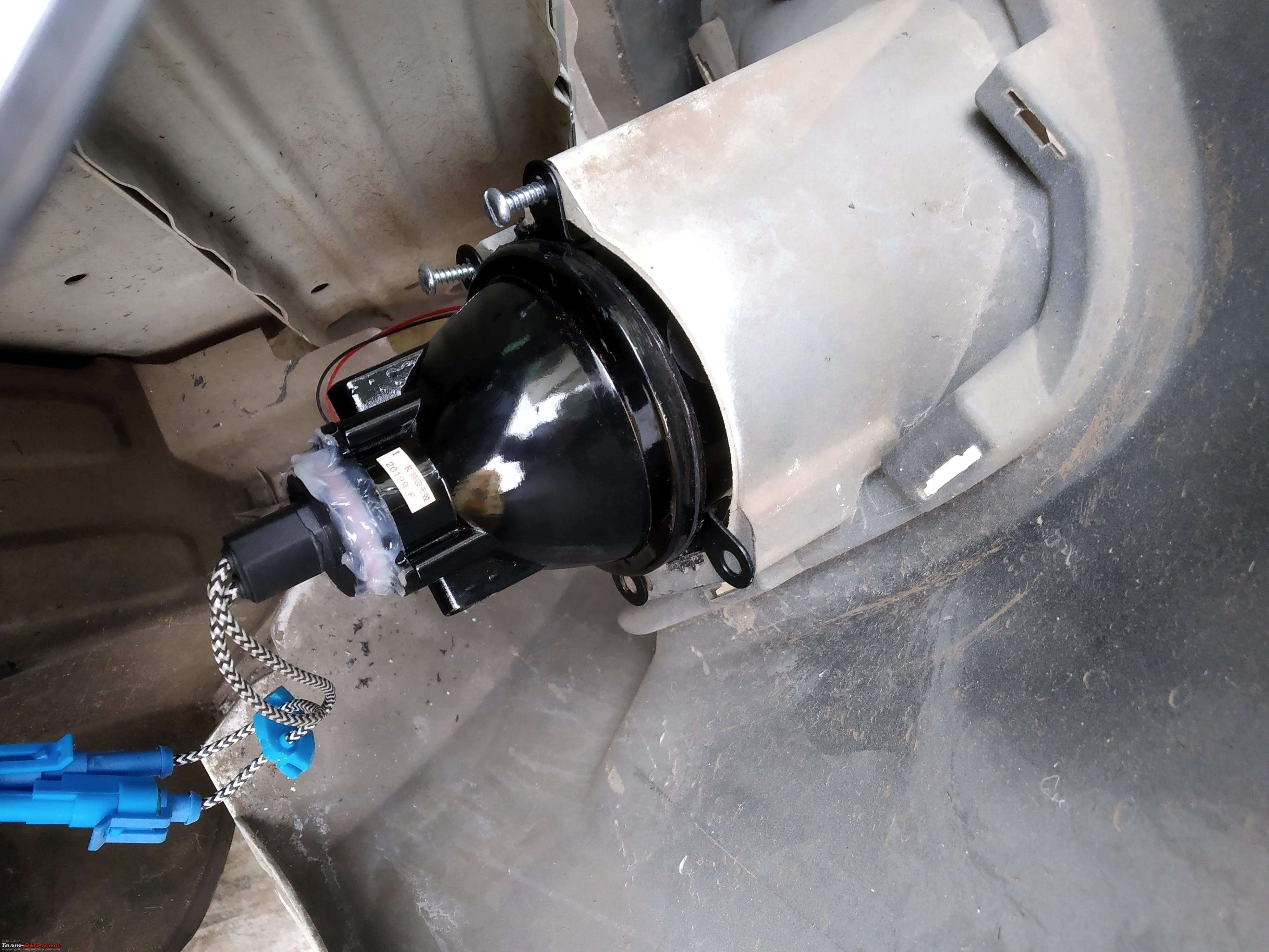
| Distinguished - BHPian | re: DIY - Maruti Alto K10 - HID Fog Light Installation Step 2 - Installing the fog lights in place Preparing the fog light shroud. The my Alto didn't have stock fog lights. It has a black shroud/bezel around the fog lights housing. However - its center doesn't have a removable cap. Its a complete single piece molded part on both sides. This means we have to carefully cut the central circular part to make a hole from which the projectors will peep out. Do it well for a flush fit. Otherwise it might leave ugly gaps / uneven cuts. The shroud is held in place simply by press fit clips. Use a soft spatula to push into edges & undo the clips. Take out the shrouds. Use a drill to make sufficient amount of holes around the circle & then use a hot nail / hacksaw blade to cut through the soft thermoplastic. I used a spare broken small hacksaw blade I have at home for such melting purposes.
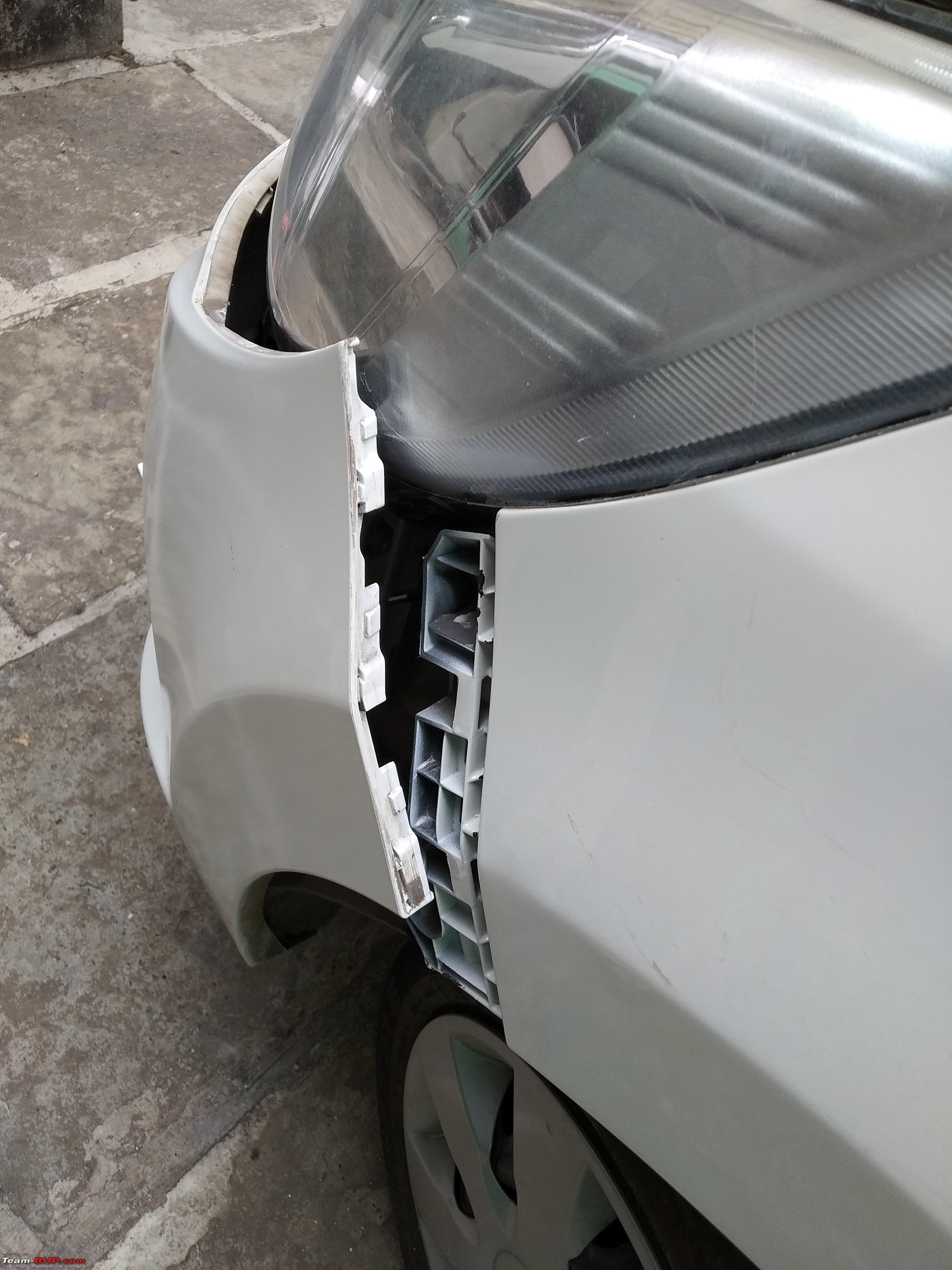
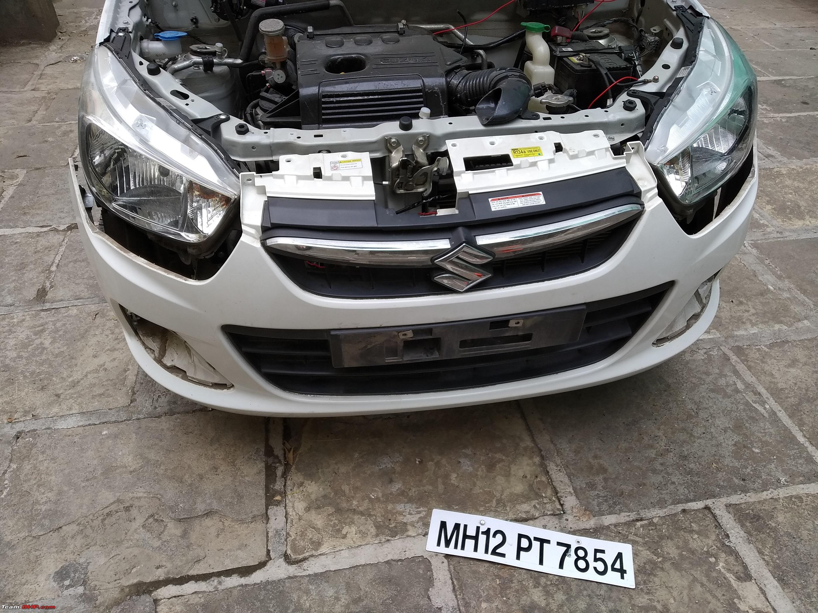
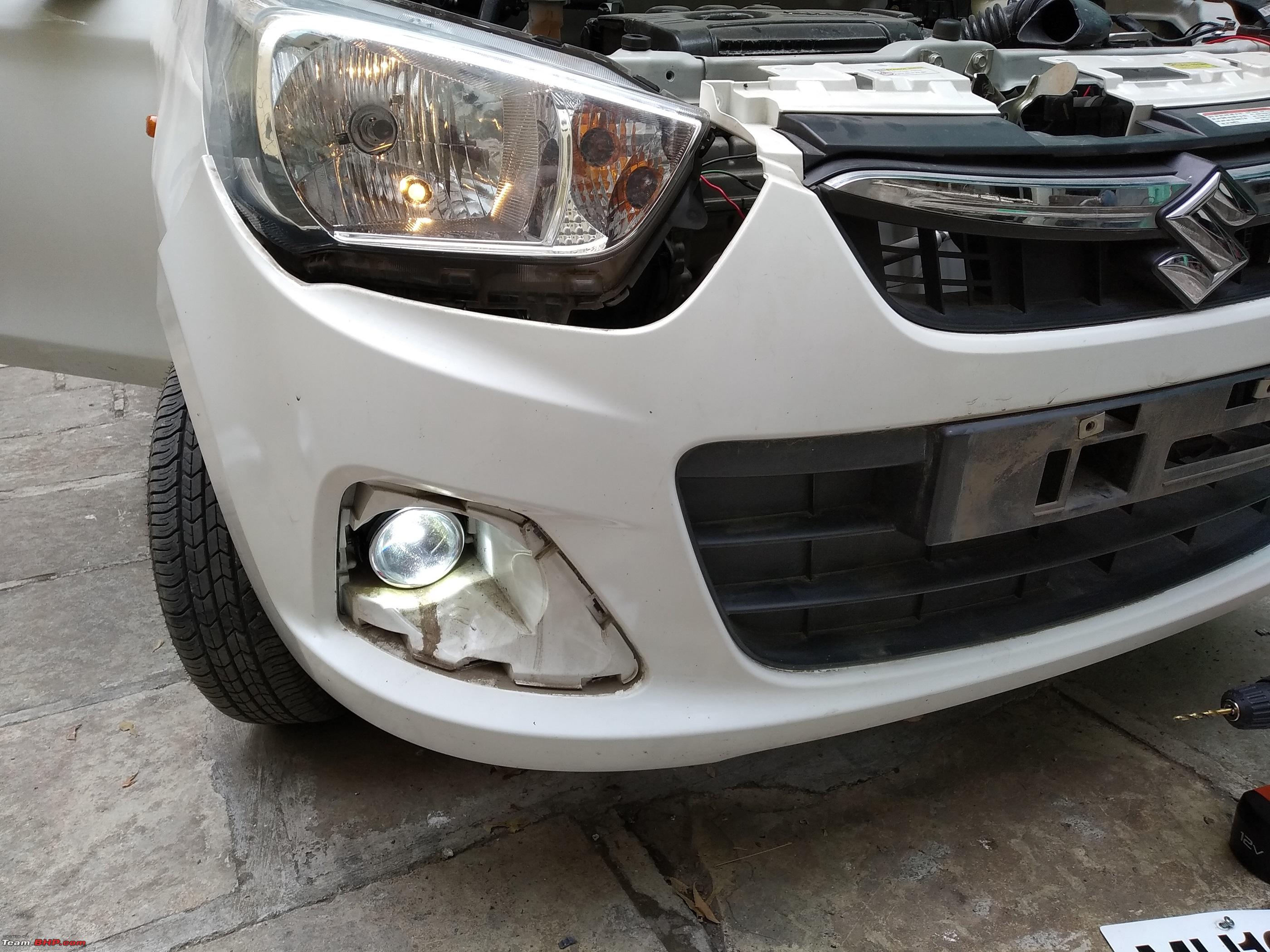
Removing the front bumper - The fog light housings have 3 screw holes each and 1 dummy flat. The screw holes are on the inside of the bumper and not accessible from front. Hence - bumper removal is an absolute must.
Installing the lights -
Last edited by Reinhard : 30th December 2019 at 12:54. |
|
| (17)
Thanks
|


| The following 17 BHPians Thank Reinhard for this useful post: | digitalnirvana, Drbhavesh, GTO, hmansari, InControl, jailbird_fynix, Leoshashi, N33raj, Prakritij, Simat, SmartCat, smuniswami, Sophomore, THE_DRIFTER, TROOPER, vaasu, VinodDevil81 |
|
30th December 2019, 12:26
| #4 |
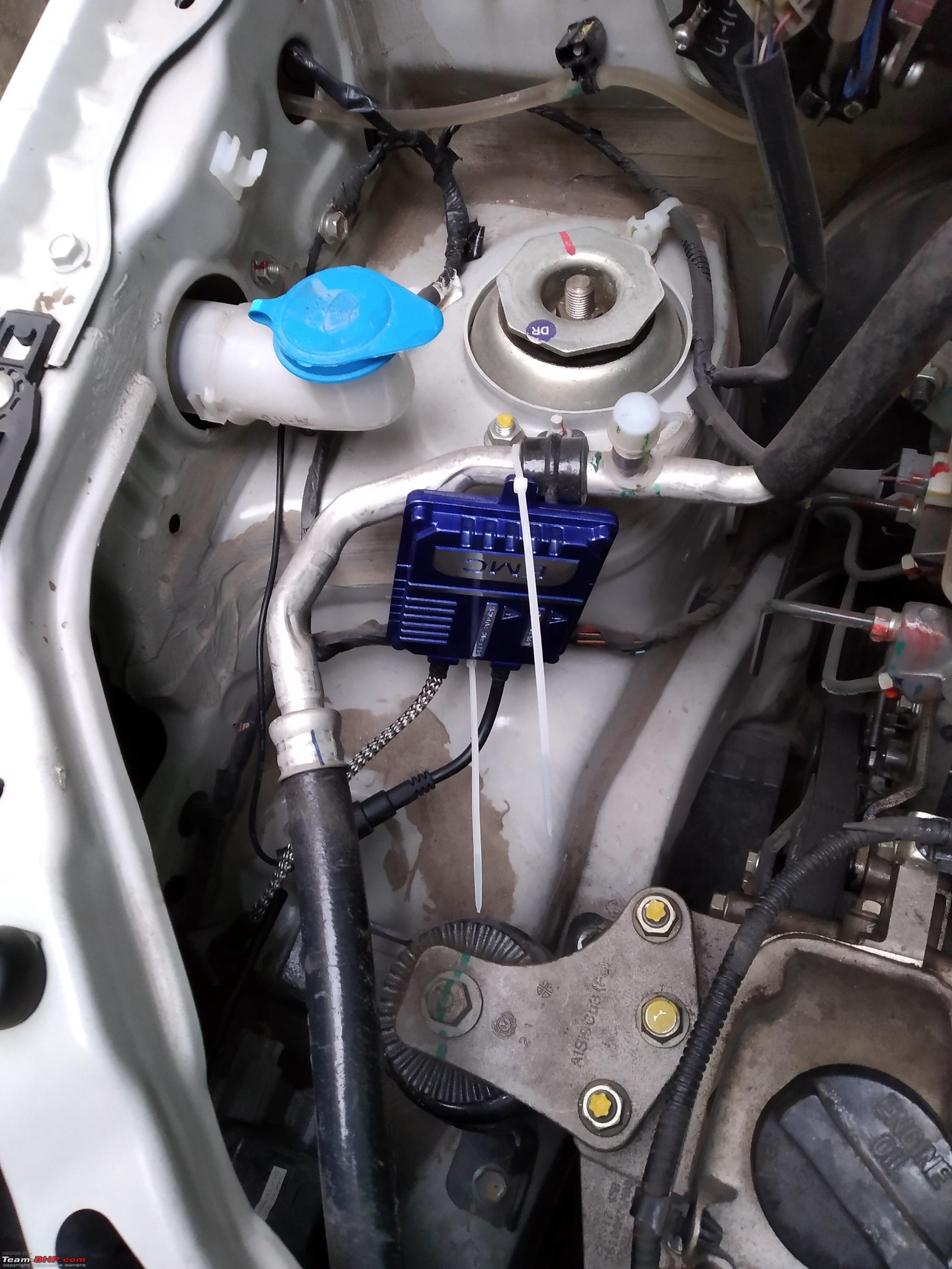
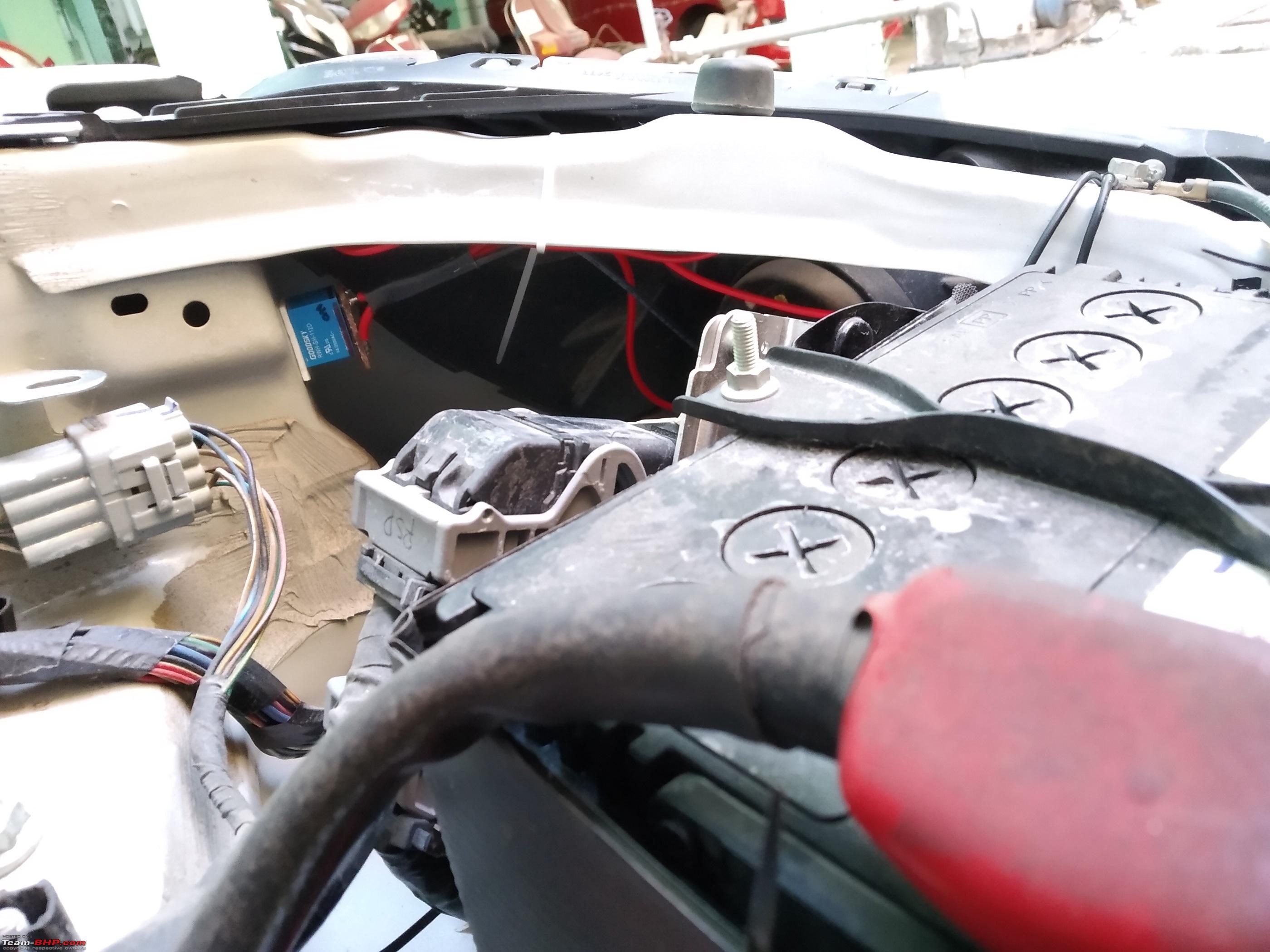
| Distinguished - BHPian | re: DIY - Maruti Alto K10 - HID Fog Light Installation Step 3 - Completing the wiring connections & test This bit is quite simple. Hard work is all done in the step earlier to be honest.
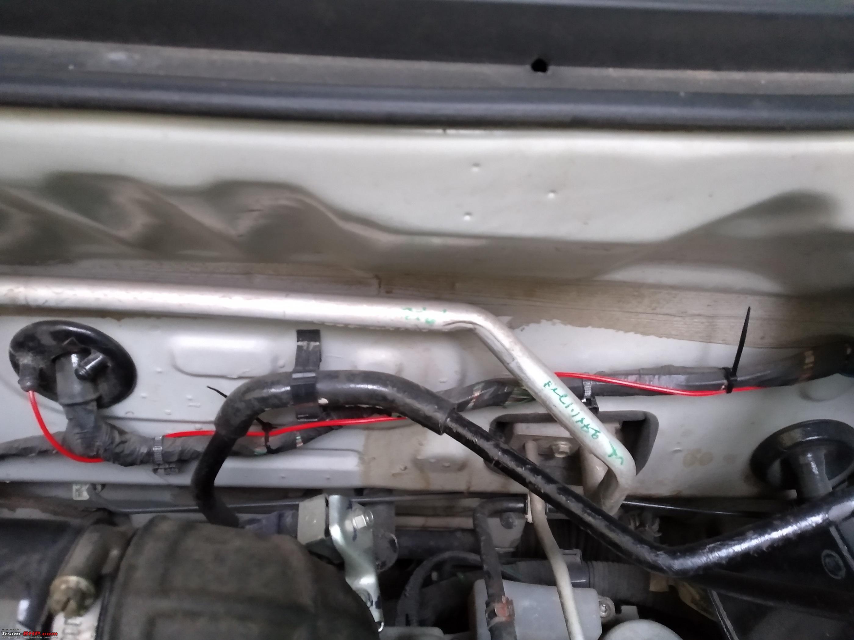
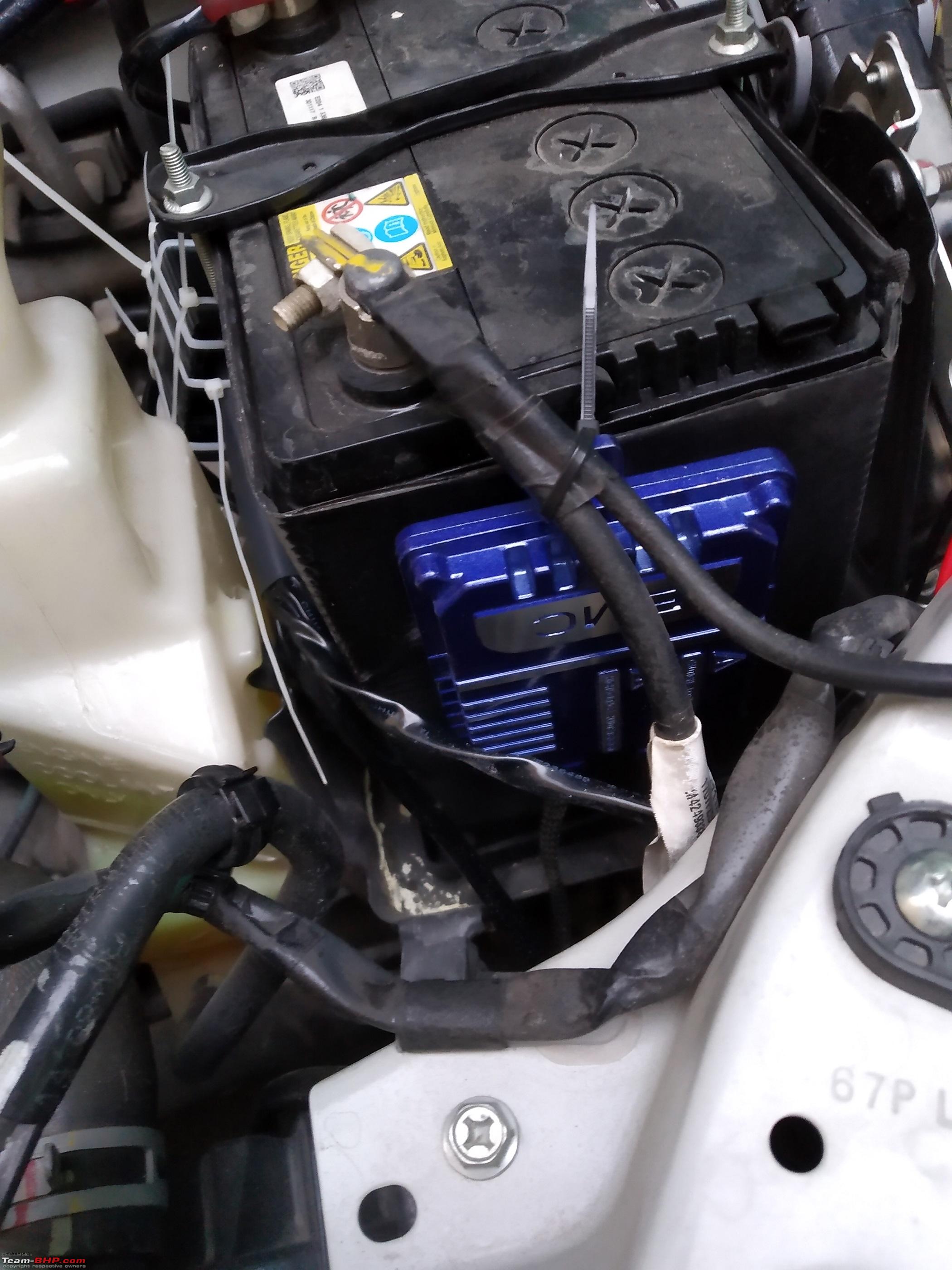
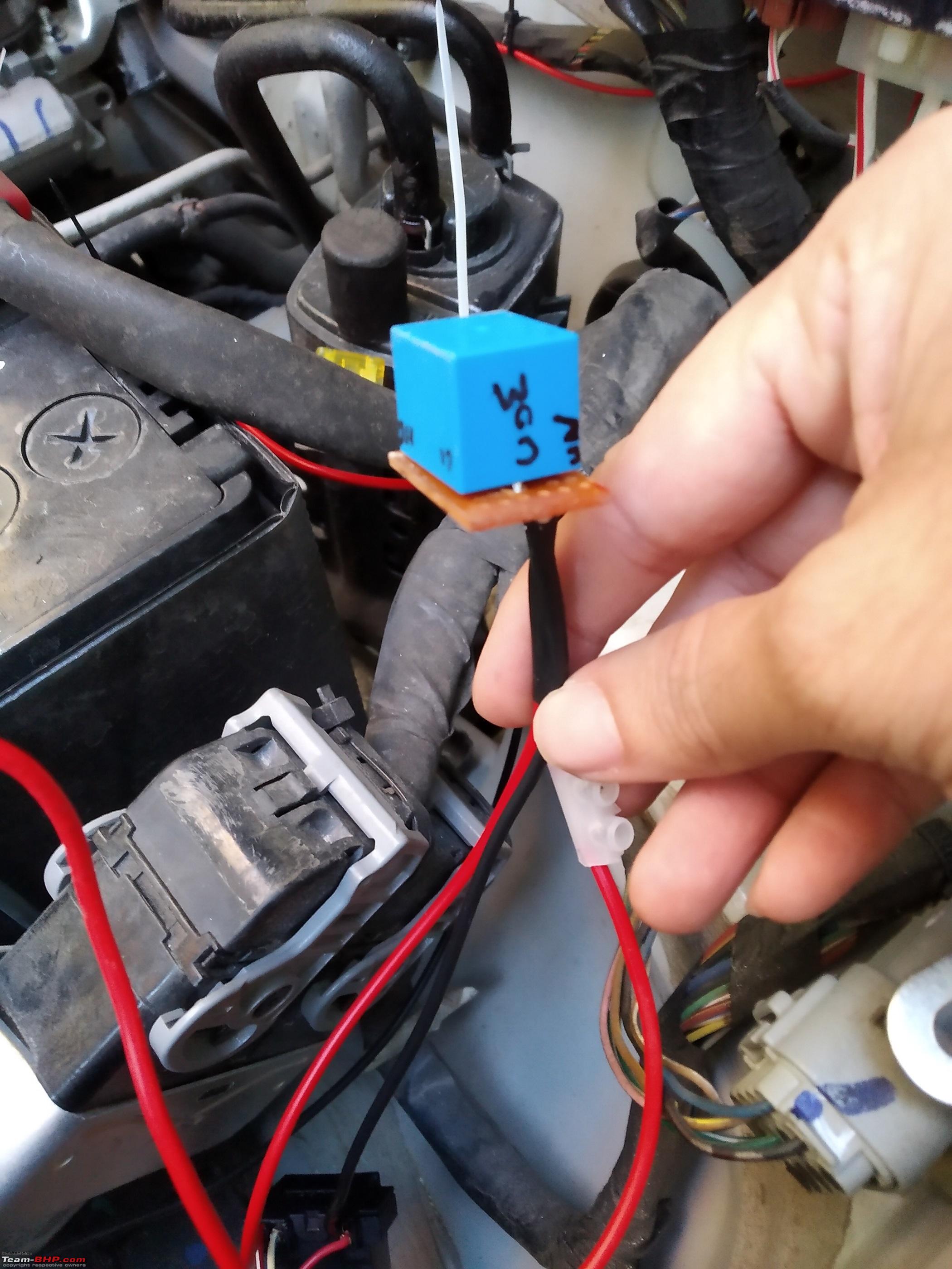
A couple of random tests - The light throw is very good. 5500K seems to be working very well in city. I tried it a couple of times in darkness. Illumination is very good. Excellent cut-off & light coverage. Its an absolute must for any car really. Considering it costs lower than 7000 INR and a few hours. Lighting is one of the vital safety components of a car & can actually avoid an accident effectively. I'll recommend this upgrade any time. Will shoot & add video tests when I get time. 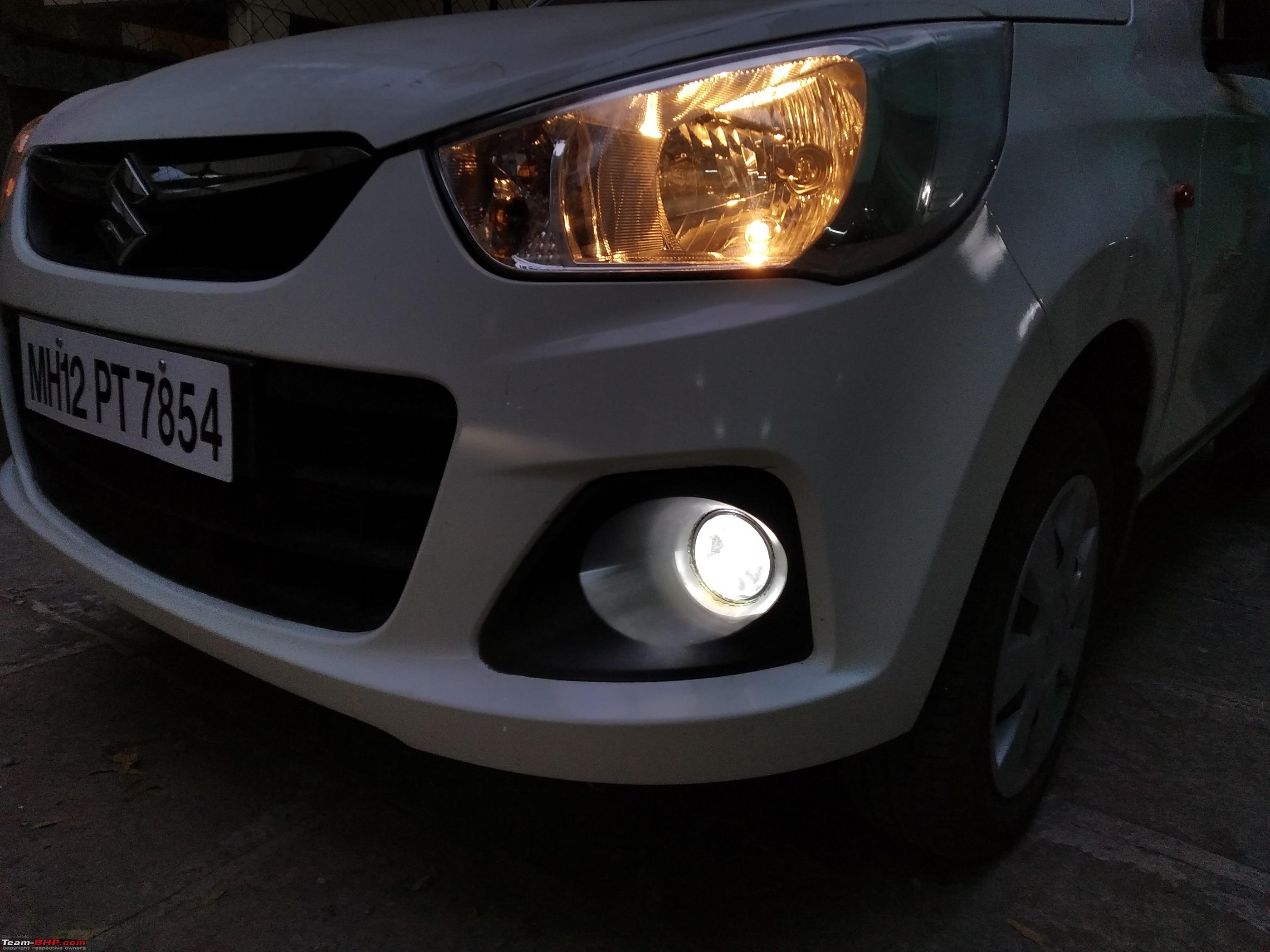 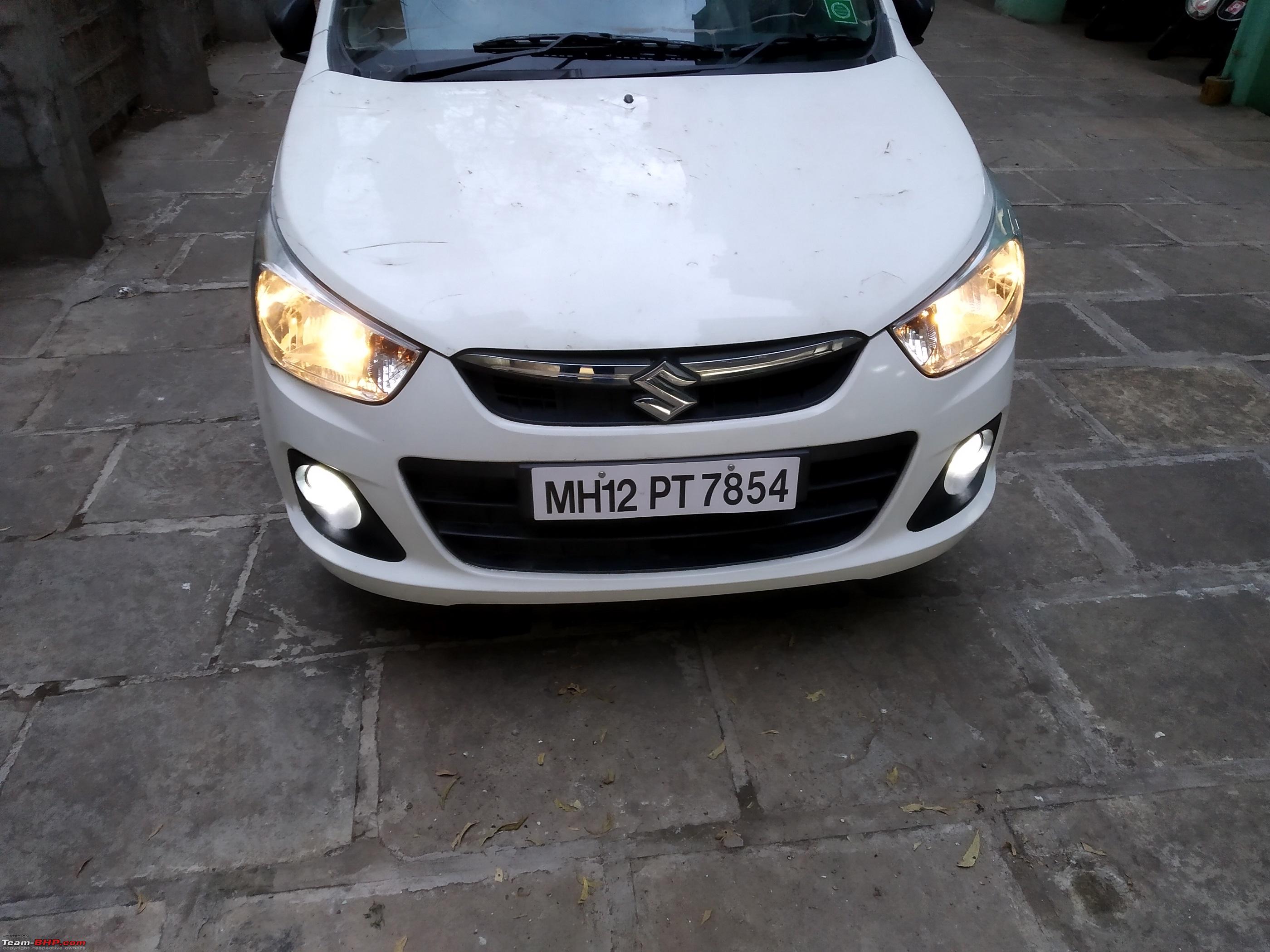 Step with extra relay! Avoidable. Like mentioned earlier, due to the negative switch in the car, the headlamp high-low pins get power when the light is off / ignition is off. The switch shorts the ground with them, thus disconnecting the circuit. My relay harness has a separate ground wire that I had already connected with solenoids. This meant, the solenoids were activated when car was off, if hooked into high beam of H4 headlamp. I worked around it using a 12V relay extra in the circuit. This relay sends power to the solenoids on high beam only when the actual high beams are on. Otherwise keeps the circuit open.
Note - this extra step can be avoided by running dedicated ground wire from the solenoids of both projectors. Simply hook that ground wire with GND pin of H4 socket & red wire with high beam of the H4 socket. That will avoid the hassle of this extra relay. Last edited by Reinhard : 30th December 2019 at 17:57. |
|
| (27)
Thanks
|


| The following 27 BHPians Thank Reinhard for this useful post: | --gKrish--, akshay81, ashis89, condor, Desmosedici, DevilzzzzOwn, digitalnirvana, fiat_tarun, GTO, hemanth.anand, hmansari, InControl, jailbird_fynix, KPR, Prakritij, PraNeel, self_driven, sharktale, Simat, SmartCat, smuniswami, somspaple, THE_DRIFTER, TROOPER, vaish9925, VinodDevil81, yesyeswe |
|
30th December 2019, 21:35
| #5 |
| Team-BHP Support  | re: DIY - Maruti Alto K10 - HID Fog Light Installation Moving thread from Assembly Line to DIY forum. Thanks for sharing, Vikas! |

| (5)
Thanks
|
| The following 5 BHPians Thank SmartCat for this useful post: | digitalnirvana, GTO, Reinhard, thenomad, THE_DRIFTER |
|
30th December 2019, 22:39
| #6 |
| Senior - BHPian Join Date: Sep 2019 Location: BLR
Posts: 1,104
Thanked: 3,051 Times
| re: DIY - Maruti Alto K10 - HID Fog Light Installation Hi, nice DIY. Can you add pics of the fogs' light with and without the low beam please? Thanks! |
|
| (2)
Thanks
|
| The following 2 BHPians Thank TheHelix0202 for this useful post: | Reinhard, THE_DRIFTER |
|
31st December 2019, 11:30
| #7 |
| Senior - BHPian Join Date: Feb 2018 Location: Chandigarh
Posts: 1,146
Thanked: 3,309 Times
| Re: DIY - Maruti Alto K10 - HID Fog Light Installation Nicely explained. Just take one precaution, screw down the ballasts instead of using zip ties. These zip ties deteriorate and become brittle over time. I've experienced this in my older car where the zip ties broke in a couple of years and left the ballast hanging loose inside the engine bay. |
|
| (4)
Thanks
|
| The following 4 BHPians Thank self_driven for this useful post: | digitalnirvana, Reinhard, THE_DRIFTER, yesyeswe |
|
31st December 2019, 13:03
| #8 |
| BHPian Join Date: Jul 2019 Location: Bijnor/Delhi
Posts: 104
Thanked: 149 Times
| Re: DIY - Maruti Alto K10 - HID Fog Light Installation Great DIY there and a nicely written guide. I've this setup installed in both of my cars and I can vouch for how amazing and worth it is, makes headlights look like candles and gives that much required confidence while driving at night. Last edited by shivamk11 : 31st December 2019 at 13:18. |
|
| (3)
Thanks
|
| The following 3 BHPians Thank shivamk11 for this useful post: | digitalnirvana, Reinhard, THE_DRIFTER |
|
2nd January 2020, 14:35
| #9 |
| BANNED Join Date: Feb 2004 Location: Goa India
Posts: 196
Thanked: 219 Times
Infractions: 0/2 (10) | Re: DIY - Maruti Alto K10 - HID Fog Light Installation Reinhard, I have been following your threads for Tata Nexon and Alto for HID Kits. Since you have experience both the kits which one would you recommend the OSRAM or the Crystal Eye HID? Could you provide feedback in terms of quality and time taken to reach the peak for full brightness |
|
| (1)
Thanks
|
| The following BHPian Thanks Gurudatta Nayak for this useful post: | Reinhard |
|
3rd January 2020, 15:41
| #10 | ||||
| Distinguished - BHPian | Re: DIY - Maruti Alto K10 - HID Fog Light Installation Quote:
Quote:
For now - the ballasts are mounted with strong 3M tapes. The zip tags are back ups to ensure minimal vertical weight on the 3M tapes. Quote:
Quote:
An apple for apple comparison won't be possible between the Osrams and the CrystalEye HIDs I have. Simply because one is 35W and the other is 55W. There is an easily noticeable difference between the two in illumination and throw. When to go with 35W Osram If one is looking for just conversion kit in an existing projector low beam head lamp - I will still recommend the 35W Osram kit. Why? -
Using a 55W conversion kit on stock harness will work on cars with canbus adapter. However, the startup surge on a 55W HID is quite high & the stock wiring may not be designed for it. I suggest changing the low beam fuses to higher current in that case. But this is not something I recommend. I don't like using higher power devices on stock wiring that is rated and designed for lower ratings. When to go for 55W Projector fog light setup If one doesn't have stock projectors in headlamp low beam, then conversion kit isn't of any use anyway. Then the only option left is installing projector fog lights if the car has round housings. In this option - I'll always go with a 55W HID kit (Blaze / IPHCar / CrystalEye). It has excellent output, real VFM & since it runs on separate relay harness with clean current from the battery, it runs minimal risk to stock wiring. The IPHCar projectors are also good and provide a very crisp throw with cutoff. In this setup - I recommend using the fog lights only as fog lights when needed or instead of headlights. Using the stock halogens + 55W HIDs literally doubles the load on the alternator and battery. Its not something we should do all the time unless necessary. Lower load ensures better alternator health and battery life in general. Hope this helps. | ||||
|
| (5)
Thanks
|

| The following 5 BHPians Thank Reinhard for this useful post: | digitalnirvana, hemanth.anand, manjunag, TheHelix0202, VinodDevil81 |
|
3rd January 2020, 17:26
| #11 | |
| Senior - BHPian Join Date: Sep 2019 Location: BLR
Posts: 1,104
Thanked: 3,051 Times
| Re: DIY - Maruti Alto K10 - HID Fog Light Installation Quote:
| |
|
| ()
Thanks
|
| |
|
4th January 2020, 10:49
| #12 | |
| Distinguished - BHPian | Re: DIY - Maruti Alto K10 - HID Fog Light Installation Quote:
 | |
|
| (1)
Thanks
|
| The following BHPian Thanks Reinhard for this useful post: | TheHelix0202 |
|
26th May 2020, 20:22
| #13 | |
| BHPian Join Date: Apr 2020 Location: Surat/Mumbai
Posts: 31
Thanked: 34 Times
| Re: DIY - Maruti Alto K10 - HID Fog Light Installation Quote:
Now, the way you have drawn power from leveling switch, I am planning to draw power by tapping from fuse box in the passenger compartment. So, 1) White and brown wires will be connected to stock fog lamp socket. 2) Wire from fuse box will be the the power input for 2nd fog lamp switch. 3) Output wire from the switch will be connected to blue wire. Do you think this will work? | |
|
| ()
Thanks
|
|
27th May 2020, 09:40
| #14 | |
| Distinguished - BHPian | Re: DIY - Maruti Alto K10 - HID Fog Light Installation Quote:
| |
|
| (1)
Thanks
|
| The following BHPian Thanks Reinhard for this useful post: | Drbhavesh |
|