Note: All the DIY/Modifications done to the car are for my own convenience. None of the parts used are sponsored by any brand whatsoever, neither am I related to the seller or the company in any manner. The whole purpose of this DIY's is to help other Bhpians/guests find solutions to common problems they may face. I will not be held responsible for any warranty issues you may face after following my DIY's. I'll try my best to help and provide all the support I can.
I was always fascinated by how the puddle lamps worked, and how useful they were during monsoons and when you have parked your car in a dark place. While I was washing the car one day I noticed a small cover under the ORVM's. After using a flat head screw driver and prying it out I found that there was enough space to add a puddle lamp and there was a hole through which the mirror wires passed, the area was very limited but now the itch to add a puddle lamp had started. :D
First I thought maybe the Indonesian model gets these lamps and MS has removed them for the Indian model. But after searching online I couldn't get anything. After searching a lot on AliExpress I found replacement LED puddle lamps for VW and Ford vehicles but none for the shape and size that the Ertiga had, they were either too big or not of the exact shape I wanted.
While searching I came across these lamps, they are compact, bright and have the same fitting as we have for reverse parking sensors. (Drill a hole and push to fit).
The size turned out to be exact for the space available underside the mirror cover. After taking some more measurements I ordered the lights. The space (height) available is approximately 26mm with some 1mm here and there to spare.
Link to the item I have used: (I went with the flood type because of the light spread it offered as opposed to the focused one. The lights are waterproof and have a metal casing and they are heavy.)
https://www.aliexpress.com/item/2PCS...3f1c4c4dQmEbdM
If you are looking for a more expensive and fancy alternative, like the new BMW's: (I have not used these lights and do not know how they will work and what output they will give, I found these during my search, anyone interested can take a shot at it.)
https://www.aliexpress.com/item/-/32...1b962e0eqrcKtn
If you are looking for a cheaper alternative: (This lights are cheaper but are a little bit longer in length and they have a focused beam as opposed to the flood type that I wanted. Not sure about the quality of these bulbs nor the waterproof rating. The length of this light is ~26mm so you have to be careful when purchasing it, there is a possibility it may not fit the area.)
https://www.aliexpress.com/item/High...4fce4c4di70jtW
I got the lights in 25 days with free shipping via China Post Registered Mail.
Before we begin this DIY, I would like to mention that since MS shares a lot of parts with other vehicles of its stable, they have done the same with ORVM's. The second generation Swift, Swift Dzire and Breeza have the same ORVM's as the Ertiga. Out of these three I have checked the Dzires's mirrors and it has the small cover needed for this DIY. Other two cars I have not been able to check. Also pry open the cover and check the amount of space available and then only go ahead. If they happen to have the required area then you can proceed below.
Since this DIY needs you to route the wires through the roof liner, the A-Pillar, the door panels, behind the glove box and behind the fuse box, I would recommend you to take some professional help to remove the parts. I took the car to my FNG to get the wiring routed as I wanted. I could have taken the glove box and other parts apart, but my dad suggested otherwise. Since the FNG is of a family friend I took the car there. Since I was working too, to route the wires, and take the parts apart I couldn't take pictures of the complete WIP, but I'll mention each step and try my best to narrate everything in detail.
Before proceeding please keep in mind that the part you are going to drill is
NOT AVAILABLE AS AN OFFICIAL PART FROM MGP, IT IS A SUB PART OF THE MIRROR ASSEMBLY. You will/ may need to buy the entire mirror assembly for that one little plastic part if things go south during the DIY. This DIY won't hamper the working of your ORVM in any manner, but will only leave an empty hole below the mirror, if in case the part breaks. Tools required:- Sharp flat head screw driver. (Small size)
- Star or Philips head screw driver.
- 20 AWG or similar size wire, 2-core, 10 meters. (Make sure the wire isn't very thin or too thick as we need to pull it through some tight spots and it should not break while pulling.)
- Hot Melt Glue Gun.
- Wire Stripper.
- Pliers.
- Wood Auger Drill Bit or Hole saw (23mm).
- Chocolate block connectors.
- Soldering Iron.
- An old bicycle wheel spoke or stiff wire to pull the wire from the rubber connectors on the doors.
- Heat shrink tubing.
- Multi-meter.
- Insulation/ Electrical tape to hold the wire in place when routing.
- An old acrylic or plywood sheet to make a template hole for the lights.
Time taken: ~2.5-3 hours.
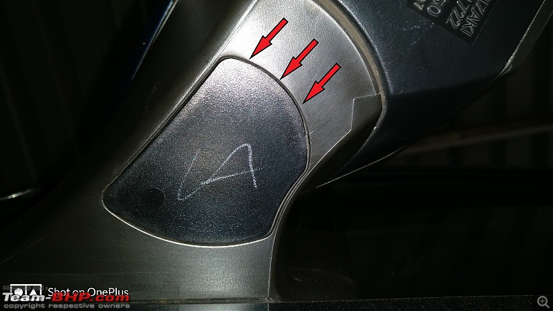
The part where the lights will be installed: 
I'll divide this DIY in parts for easy understanding.
I) Routing wire through doors and roof liner:
Opening the door panel to pass the wire through the door and out through the mirror part.
The door is held together by 2 screws and one push clip. Remove them and then lift the door from the bottom and start pulling it out slowly. There are cables connected to the controls on the driver side and passenger side.
There are two connectors for the driver side door and one on the passenger side. You may need help with holding and taking out the connectors as they are firmly fit and have a small clip that needs to be pressed in order to free it.
Driver side door panel: 
After removing the door panel you can pry out the black cover that hides the mirror screws and the hole through which we need to pass the wire. You can pull it out with fingers or a flat head screw driver from the sides.
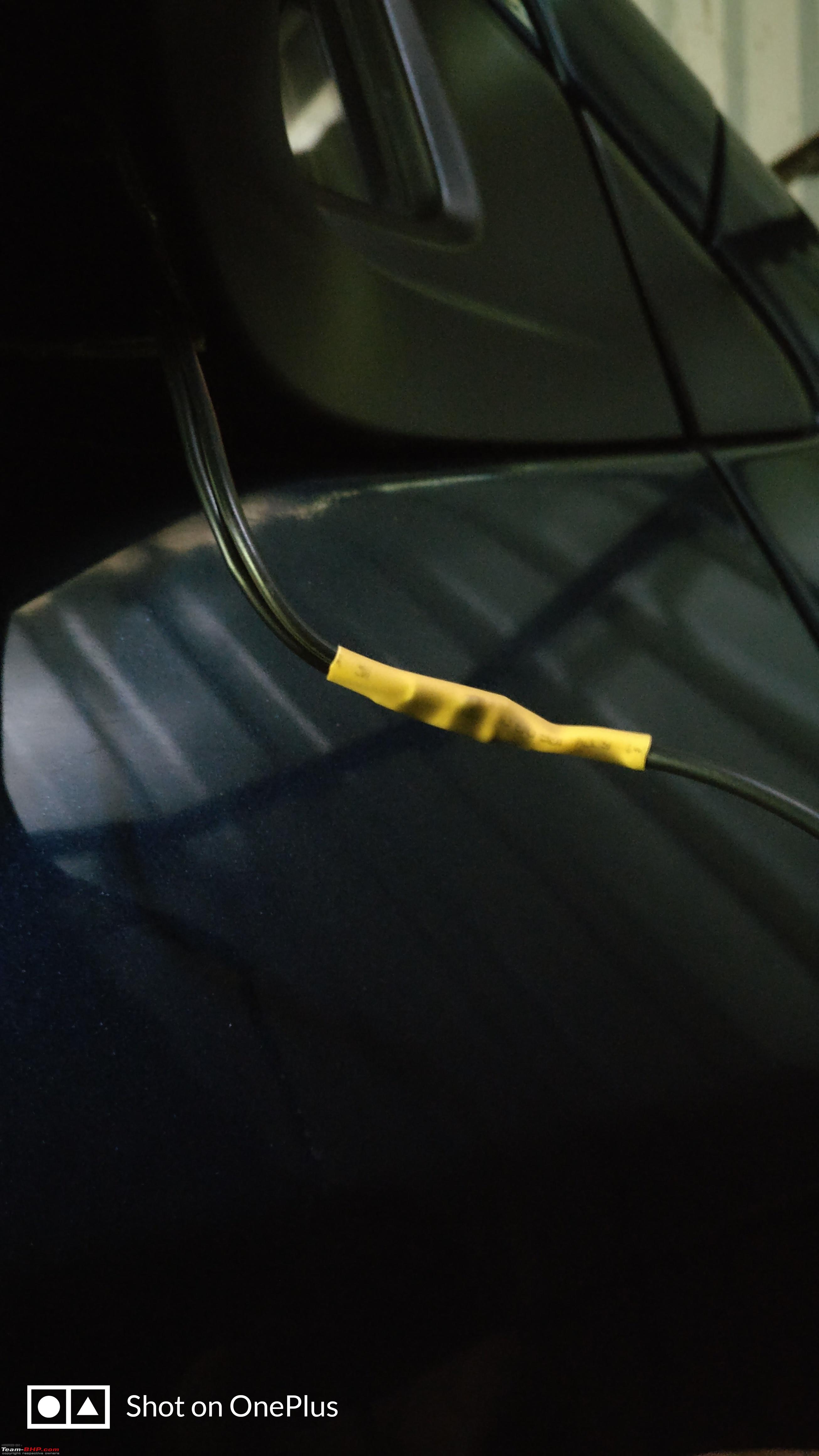
Once everything is clear push the wire through the hole and take it about 4" inches outside under the mirror, and route the remaining wire to the center of the door near the hinge where you will see the flexible rubber tubing (spring like) that has all the wires, and it passes from the door to the A-pillar.
 To open the cover, pry it with a flat head screw driver at this area, the locks are here: The wire out through the mirror cover:
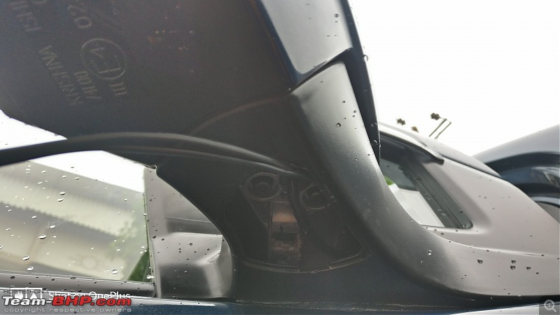
After coming near the tubing, take a stiff wire or a cycle wheel spoke and bend the top end making it round/ smooth so that it wont get stuck in the tubing when you are pushing the wire out to the other end. Fix the wire to the end of the spoke/wire and put some electrical tape to prevent it from coming out. The wire once inside through the door needs to pass through this small passage on the A-pillar. ( See the tiny red thing in the second picture near my finger, that is the wire; the place is very small so use a thin but strong wire)
Once through the tubing the real struggle begins especially for the driver side. This is where I got involved in the process and forgot to take the pictures of the WIP. stupid:
First let's begin with the passenger side, to pass the wire easily you need to take out the glove box. The glove box is hinged at two places and the hinges act as locks. Squeeze the inner side of the glove box to remove it from the hinges and pull it outward. It'll come out completely exposing the rubber pipe on the A-pillar where it enters the cabin. Since I don't have any pictures of this I am trying to explain it verbally.
The wire passing behind the glove box: 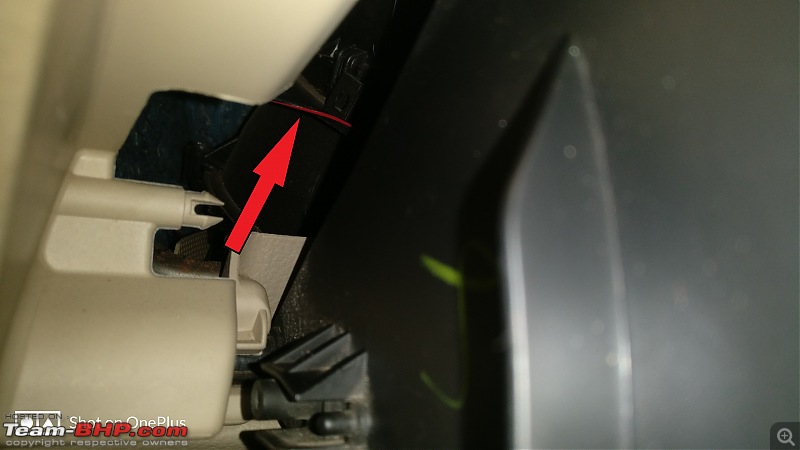
Once the wire is inside you need to take it down to the passenger foot well. This is where the power wire from the dome light and the wire for the light on the driver side will come and connections will be done.
Now comes the most irritating part, routing the wire inside the cabin through the A-pillar for the driver side. The problem is the fuse box that sits in front of the passage through which the wiring harness comes in. Hence you cannot access that area until you remove the panel below the steering wheel. It is held by two screws, one besides the hood opening latch and one on the other end. And the rest is in place with the push type clips. To open it pull the plastic panel from the bottom and it should come out. Then to pass the wire you need the spoke/wire again and put it from the inside to get it on the outside of the A-pillar. Once you are able to get your way out, fix the wire in the loop again secure it with electrical tape and pull the wire inside the cabin.
This is where I spent almost 1.5 hours trying to get the wire in.
The panel screws: 
 Wire inside the cabin:
 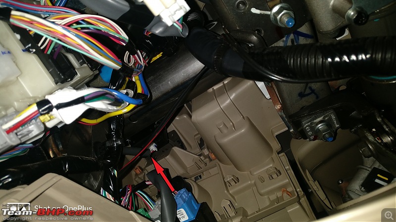 The fuse-box: (God bless the person who designed it. It is VERY difficult to access)
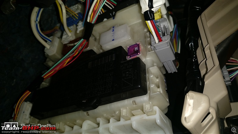
Fix the wire in place so that it doesn't interfere with the steering operation.
Wire passing across the central console to the passenger side foot well:
OBD port with blue arrow and red arrow showing the wire.

Make sure you add some identification mark on the wires to make sure which wires are for the lamps and which is the power wire.
After getting the wires inside the cabin, you need to take the power from the front dome light. The dome light is another example of bad designing by MS, they have not used a screw to hold it in place, but rather 4 oddly shaped clips that become loose the minute you pull the dome light down. To remove the dome light, put your fingers between the light frame and the roof liner and pull it down, the clips will get stuck and you need to loosen them properly. There are two wires that need to be disconnected one for the light power supply and other for the Bluetooth mic. (both denoted in red arrows)
The dome light 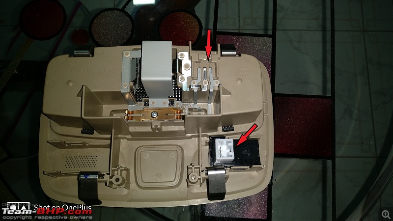
Since the dome light has the theater dimming effect, I decided to take power from it. Also this would help me in turning ON the puddle lamps when I unlock the car with the remote key. I soldered the wires on the metal guides to draw power for my lights. The right side is positive and the left side is negative.
Doing so also helped me to turn off the puddle lamps completely with the dome light switch, or keep them continuously ON.
I added a chocolate block connector to the terminals and connected the wire (during which the dome light power was disconnected) that I would be passing down to the foot well from the roof liner. I would recommend using bullet connectors instead of the connector. I have ordered the bullet connectors from AliExpress once they arrive I'll change it.
Now to pass the wire from the roof liner use the same spoke/wire again and push the starting part towards the windscreen and the wire will come out from there. Pull the necessary length of wire while keeping around 4" for connection to the dome light. Do not pull the roof liner down near the windscreen, you will damage it and it won't get back to it's original state.
Instead just push the wire in the gap and it'll stay there.
Wire passed through the roof liner: 
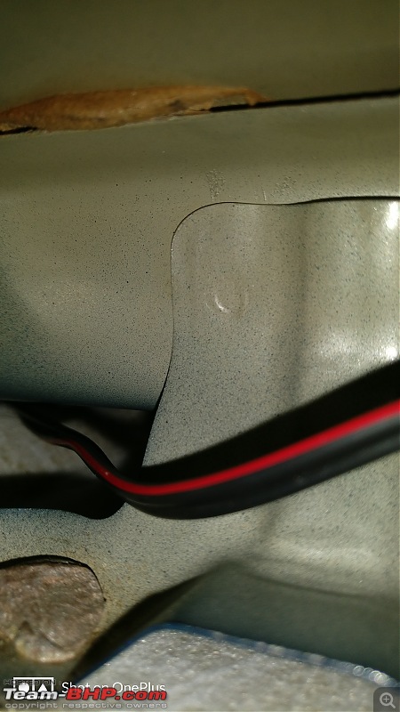
Take the wire towards the rubber beading of the door and remove the rubber beading and pass the wire through it.
Once the wire reaches the bottom you can easily move it to the passenger foot well. Now you should have three wires.
Routing the wires work is DONE!!
II) Installing the lights on the plastic cover:
Since the lights need a perfect diameter hole to sit in flush and lock properly, I tried the wood auger bit that I had on an old acrylic sheet. After the hole was done I installed the lights in it and checked how firmly they fit and if they locked in place like I wanted them to be.
Since the lights have an odd size diameter getting a hole saw in the local store was a bit difficult. I didn't need the hole saw because the wood auger I had was of the perfect size. :D
In case you are not able to get hold of one I am adding a link to the one I was going to order before I used the wood auger.
https://www.aliexpress.com/item/HSS-...648592721.html
Starting with the template drilling. This step is mandatory, I would recommend you to do it even if you have the exact diameter tool. Since you only have one chance of getting it right, take utmost care before drilling. I would also recommend to use a variable speed drill machine, so that you can drill slowly as the part is small. After making the template fix the light in it and see how well it sits.
III) Connections: Add heat shrink sleeves and connect the wires in the foot well:(The shining blue electrical tapes that you can see are to indicate the wires from the lights)
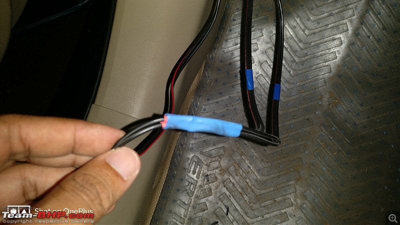
Since the lights are LED they need proper polarity to work, so make sure that there is no confusion regarding that. In case the lights don't work reverse the wires and check, before heat shrinking them with sleeves.
Follow the same wiring outside the wing mirrors and heat shrink the connections with sleeves:
 Connect the power cable to the dome light and turn the switch to ON, the lights will come ON. Now fix the cover back in place.
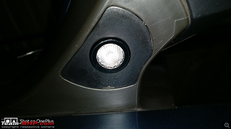
And it's done!!clap:
Some important points:- This DIY will not affect the working of the mirror in any possible way.
- Be sure to check the lights when they arrive, before proceeding with the installation.
- Take your own sweet time to drill the holes. DON'T HURRY.
- Although 10 meters of wire may be sufficient but, please buy a spare 3 meter more, because the route I took to guide the wire may not be same that you will be taking.
- Make sure to use full lengths of wire and avoid joints as far as possible.
- Keep a fevi-quick handy to stick the metal clips from the dome light.
- Be sure to keep a watch as to where they fly when you pull the lamp down.
- The methods to remove the door panel, glove box and other parts may be different for other models; and also the routing of wire. So please check before proceeding.
Last but not least thank you for bearing with me through this long DIY.
Very cleanly pulled off. I was myself too keen on this DIY for my Civic as wiring it in parallel with the dome lights would do the trick. But then the lack of space under the OVRM for placing the bulbs/lights has pulled me back.
I installed footwell lighting instead :D
Thanks for sharing this useful DIY.
Regards,
Saket.