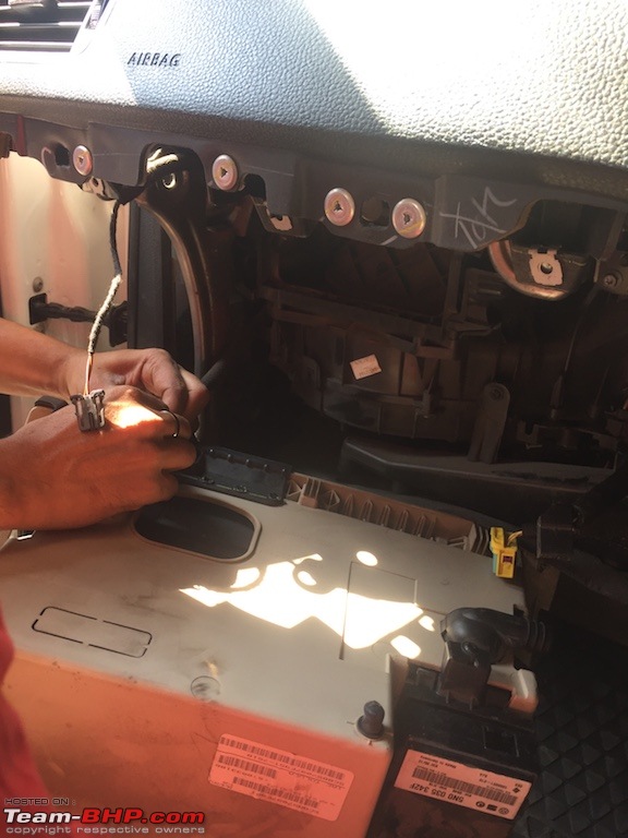
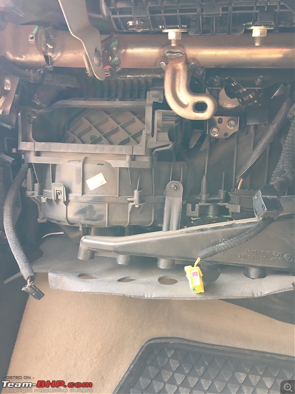
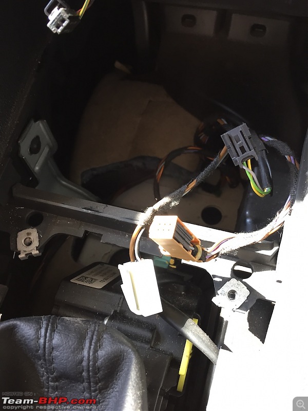
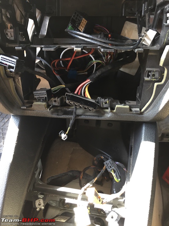
WIRING :
Now if you spare some time on this and understand diagram, then it's pretty simple. Otherwise it may confuse you. Because the diagram we used here doesn't match actual wiring diagram of PLA kit. But luckily everything works even after following incorrect diagram. phew
Seller was very helpful and he even sent wiring connections as follows.
Front bumper parking sensor cable Black T8 Plug--- Yellow T12 Plug of Parking module
T8/1---------T12/1(ground wire)
T8/2---------T12/2(firing line)
T8/3---------T12/5 Front left Green and white
T8/4---------T12/6 Middle left Green and yellow
T8/5---------T12/7 Middle Right Green and Red
T8/6---------T12/8 Front Right Green and Blue
T8/7---------T12/9 (PLA Module Left)Black and Green
T8/8---------T12/10(PLA Module Right)Grey and Green
Switch Cable
Front Parking Sensor Switch ----------Parking Module Yellow T16 Plug T6/2-------T16/13(Green and Blue)
T6/5-------T16/4(Green and While)
PLA Switch--------Parking Module Yellow T16 Plug
T6/2-------T16/9(Blue and white)
T6/5-------T16/16(Purple and white)
PLA2.0 Cable
PLA2.0 Rear Bumper Cable
White and Purple cable ---Black Plug of Parking Module T12/6(Right PLA Sensor)
Yellow and Purple cable-- Black Plug of Parking Module 12/10(Left PLA Sensor)
Red and Yellow—Positive wire of Rear Bumper sensor cable (doubling same color wire and get power supply.
brownish yellow---Negative cable of rear bumper sensor(Ground)( doubling same color wire)
We followed this diagram below. But as you can see, it is incomplete. There's no instructions for rear PLA sensor connection.
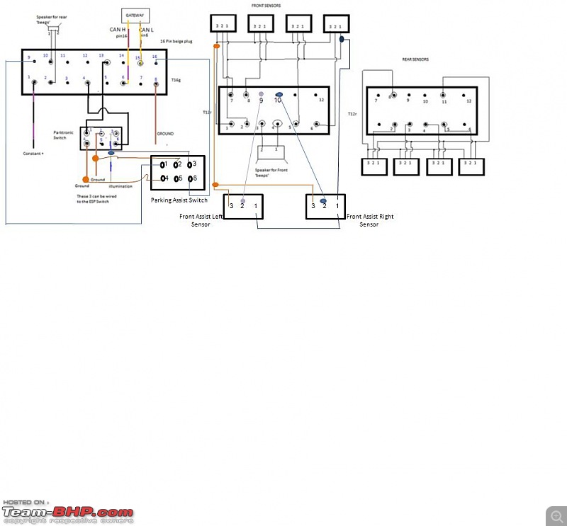
image source - vwvortex
PARK ASSIST SWITCH wiring (left side connector) for PLA module :
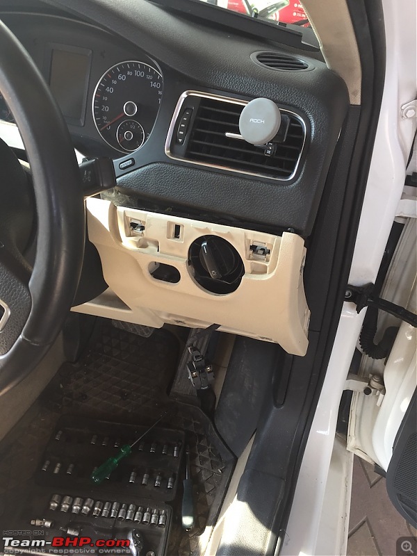
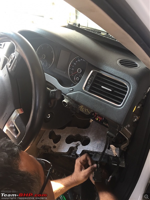
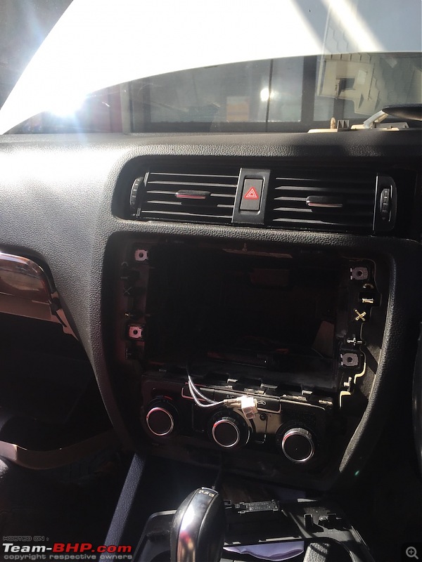
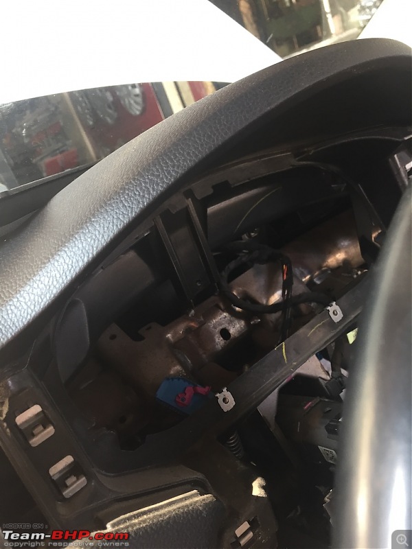
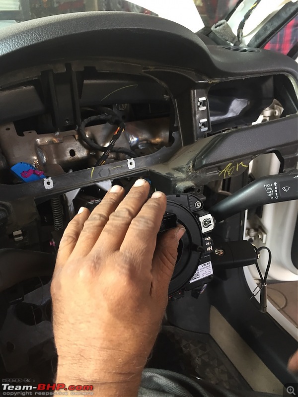
Starting with Park Assist switch wiring. First of all get this wire beneath dashboard throughout upper right corner of dashboard, so that we can connect it to PLA module.
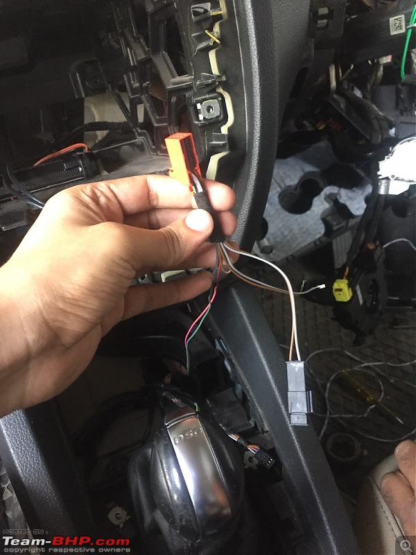
Now as you can see in the diagram, we need to tap brown(ground) and grey (illumination) wire into Park Pilot switch.
This switch comes with additional brown and grey wire connector. This can be used if you want to install TPMS (Tire Pressure Monitoring System) switch.
Now as you can see there are 2 wires coming out of switch - green and pink. Pull that cable throughout dashboard to upper right corner where PLA module is placed.
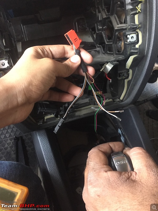
Now you need to insert 2 wires to
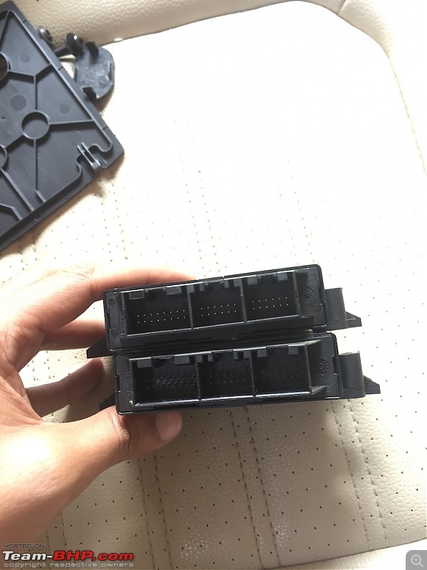
T16 (16 pin connector i.e left connector) :
PINK wire to
PIN 9 GREEN wire to
PIN 16 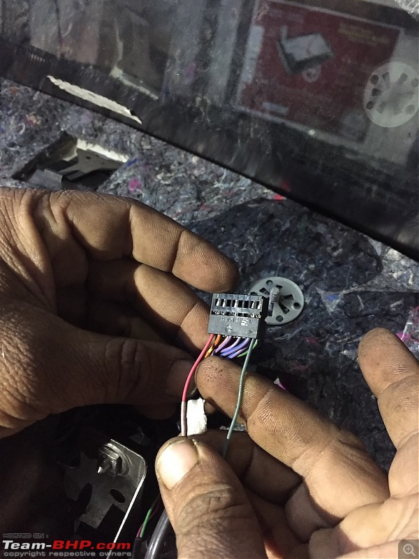
If you look closely, you can clearly see that there are marking of numbers on connector itself. Using that marking we are going to insert new wires.
So that switch wiring is completed. We will connect switch later on when we put back dashboard.
FRONT PLA SENSOR wiring (middle connector) for PLA module :
As you can see in the diagram, you just need to insert 2 wires to
T12(a) (12 pin connector i.e middle connector)
GREEN with black stripes wire to
PIN 9 GREEN with white stripes wire to
PIN 10 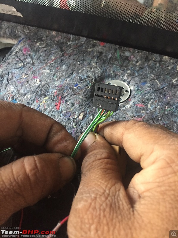
Front PLA sensor wiring is done. Now we will move on to Rear.
REAR PLA SENSOR wiring (right connector) for PLA module :
As I described earlier, if you look at the diagram there is no details given for how to connect rear PLA sensor.
So we had to check by ourselves only and finally got correct PIN numbers after several discussions.
You need to insert 2 wires to
T12(b) (12 pin connector i.e right connector)
BLUE wire to
PIN 6 BLACK wire to
PIN 10 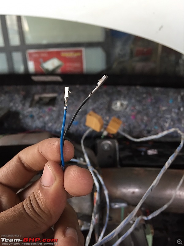
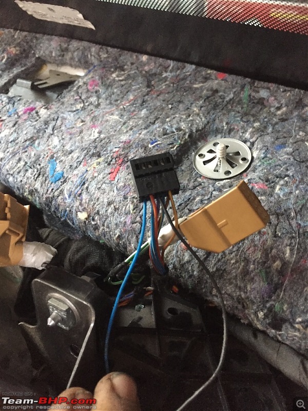
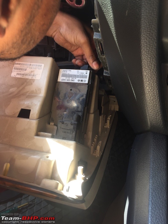
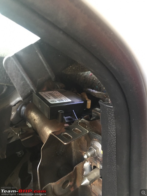
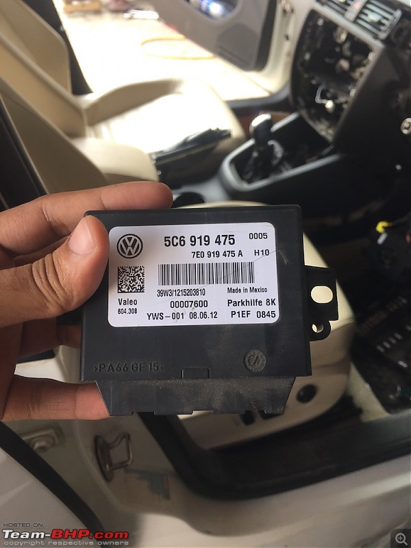
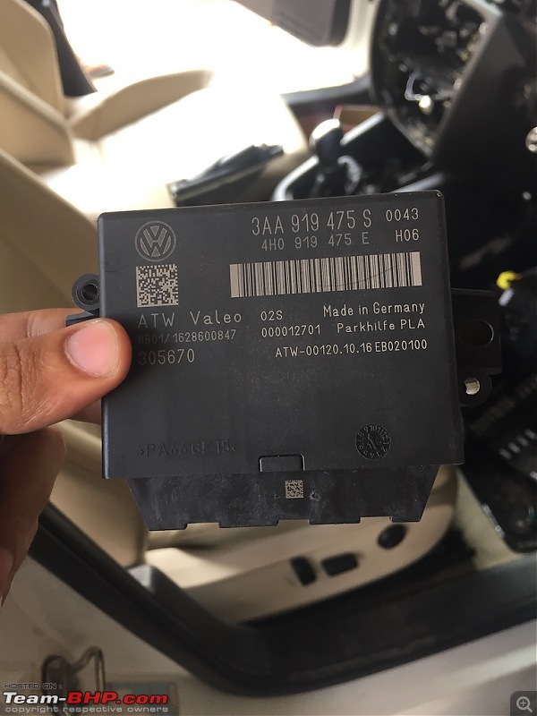
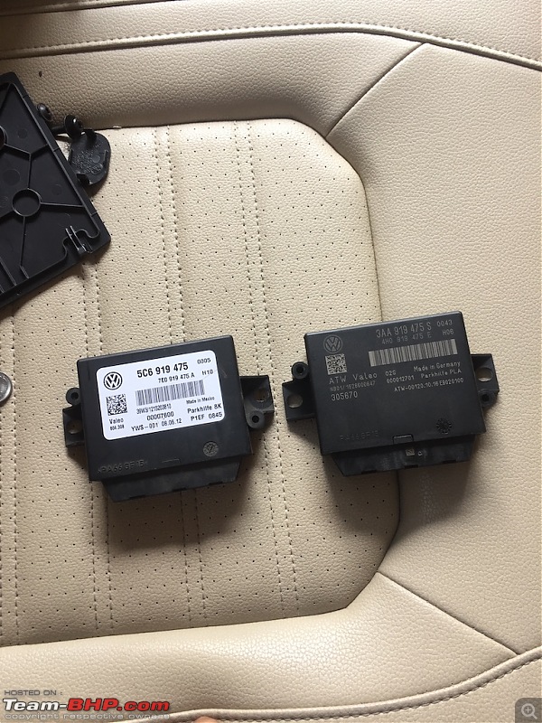
Now connect all the connectors back to PLA module and put it back in position.
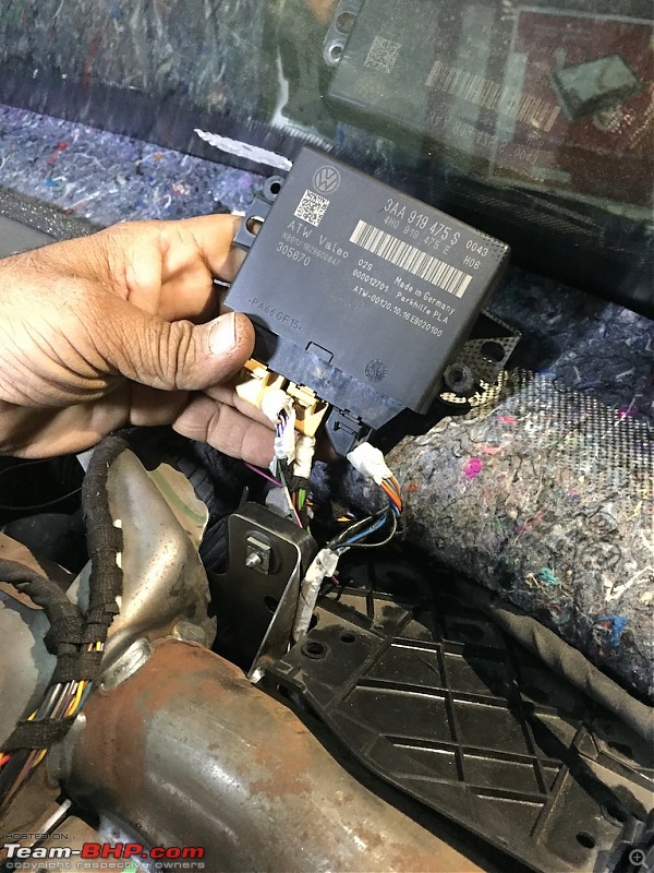
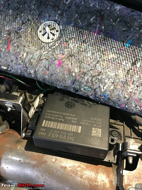
Now that we are done with PLA module wiring, we will be moving on to PLA sensor connection.
FRONT PLA sensor wiring :
Now if you look at wiring diagram, it is pretty straight forward.
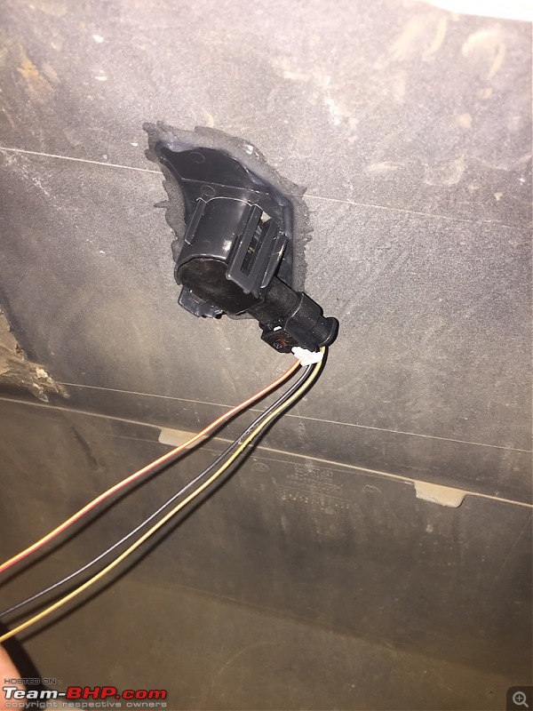
Each sensor consist of 3 wires.
LEFT PLA
One is for GROUND. (brown)
One is for SIGNAL. (green with black)
One is for POWER. (red)
RIGHT PLA
One is for GROUND. (brown)
One is for SIGNAL. (green with white)
One is for POWER. (red)
We need to tap GROUND & POWER to existing parking sensors as shown in diagram.
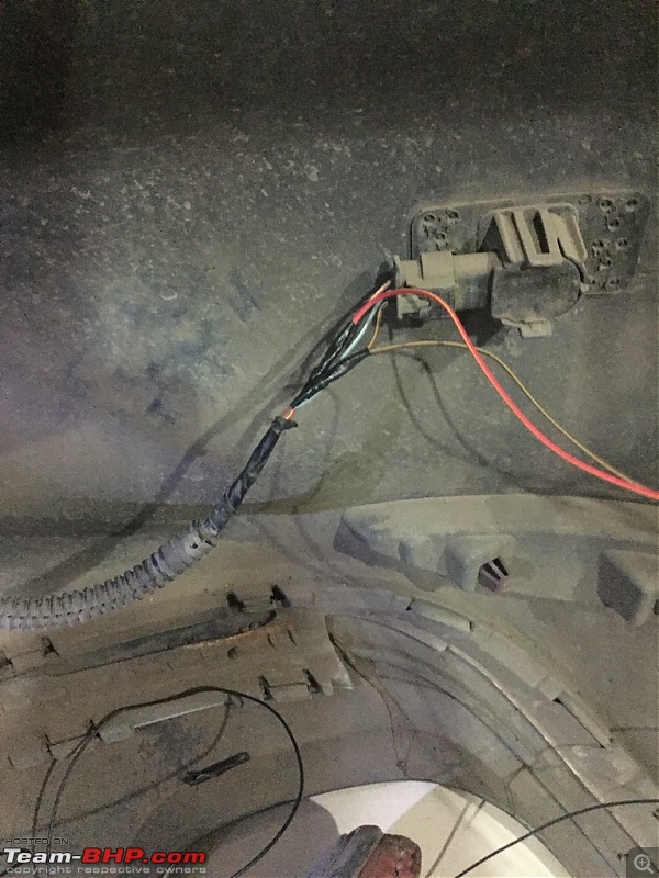
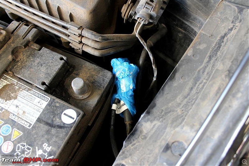
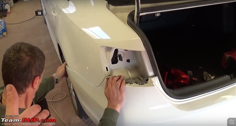
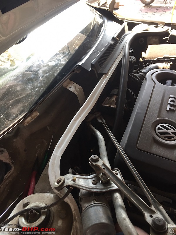
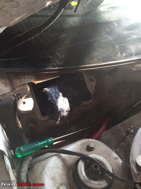
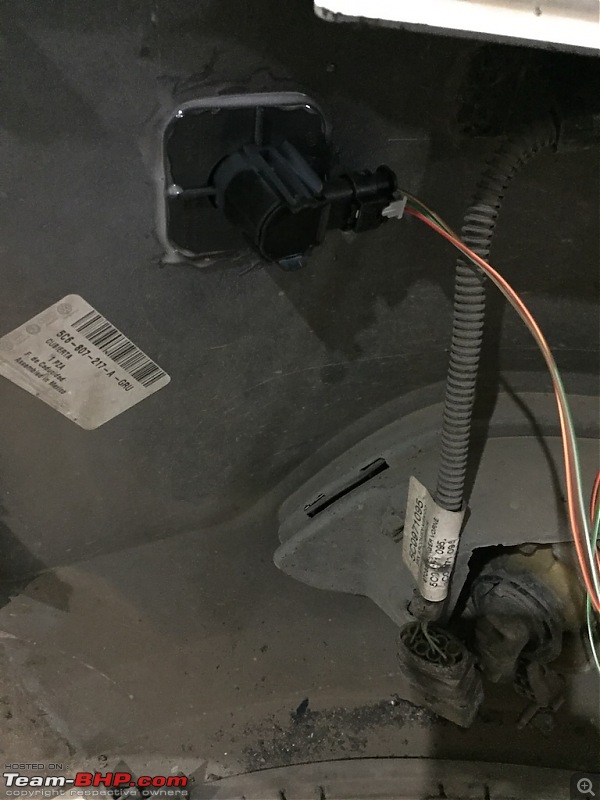
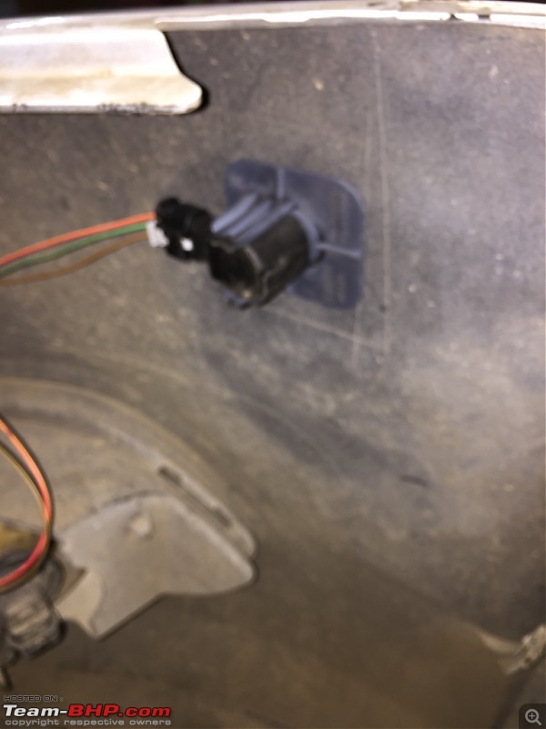
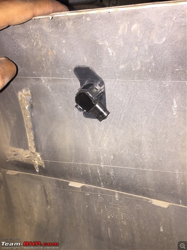
Now get 2 green wires from PLA module to front bumper from inside engine bay. You can use cloth tape for additional safety. Don't place it near any metal or engine component which gets too hot.
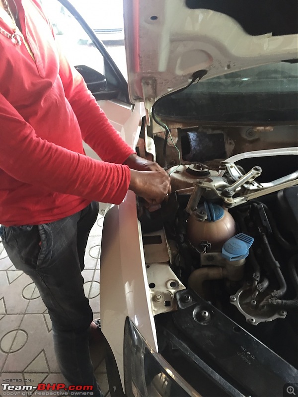
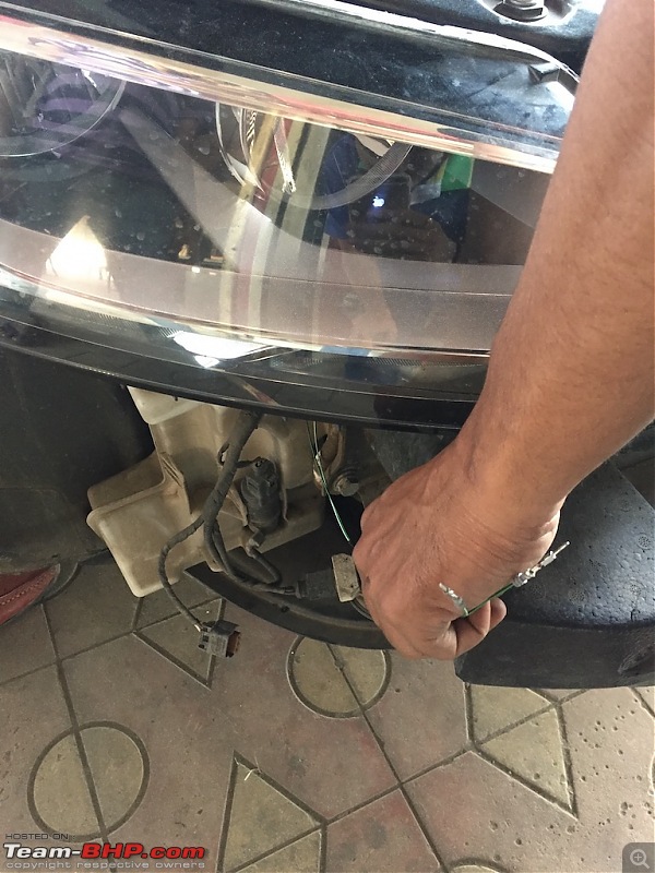
Now as you can see, wires are short. But you will find additional waterproof connectors which will give you enough length to cover both PLA sensors.
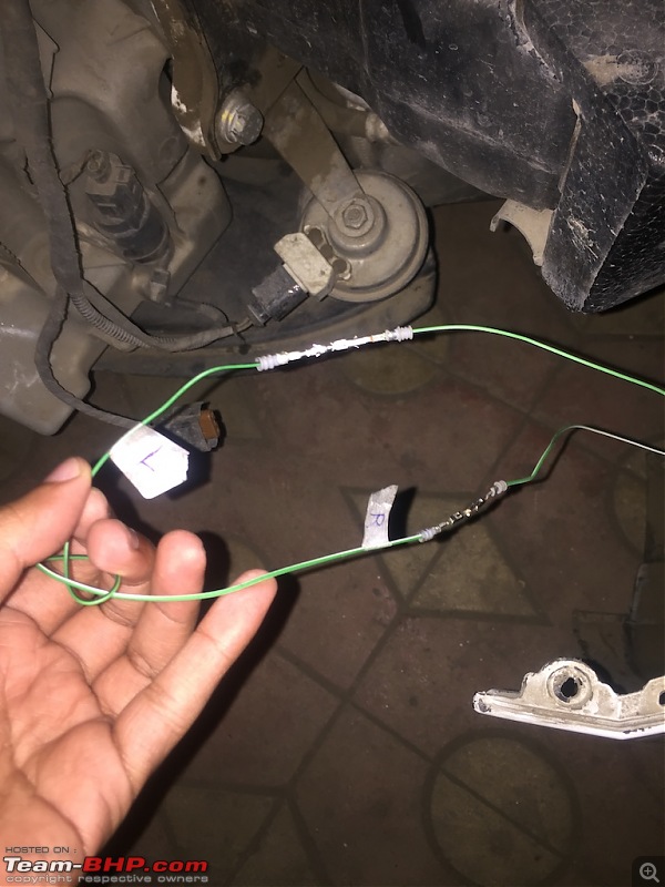
Connect
GREEN with white stripes to
FRONT RIGHT PLA sensor.
Connect
GREEN with black stripes to
FRONT LEFT PLA sensor.
Now moving on to rear PLA sensor.
REAR PLA sensor wiring :
Now if you look at wiring diagram, it is pretty straight forward.
Each sensor consist of 3 wires.
LEFT PLA
One is for GROUND. (brown)
One is for SIGNAL. (black)
One is for POWER. (red)
RIGHT PLA
One is for GROUND. (brown)
One is for SIGNAL. (blue)
One is for POWER. (red)
We need to tap GROUND & POWER to existing parking sensors. There is no diagram which shows this step but, it's similar to front sensor wiring so no issue.
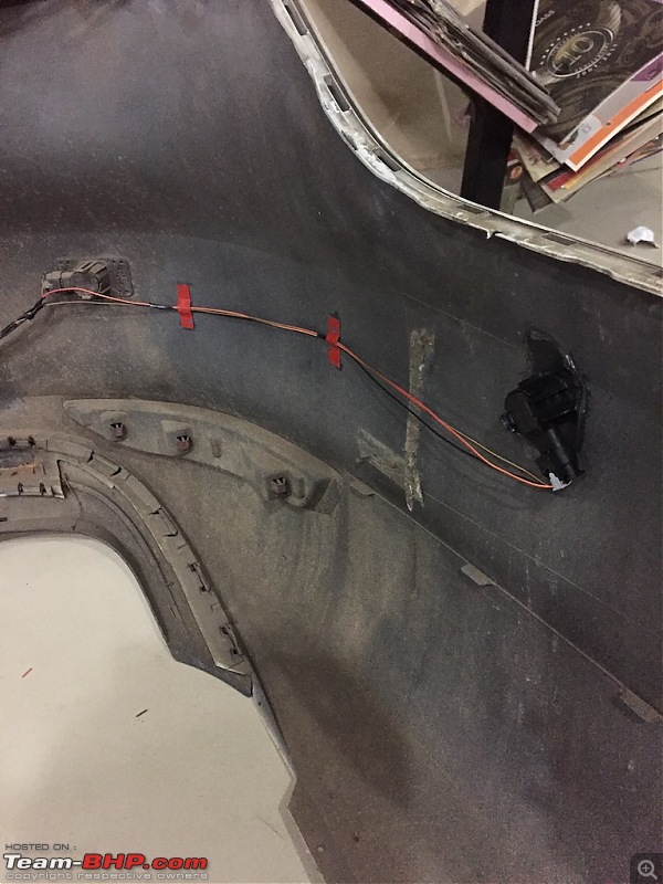
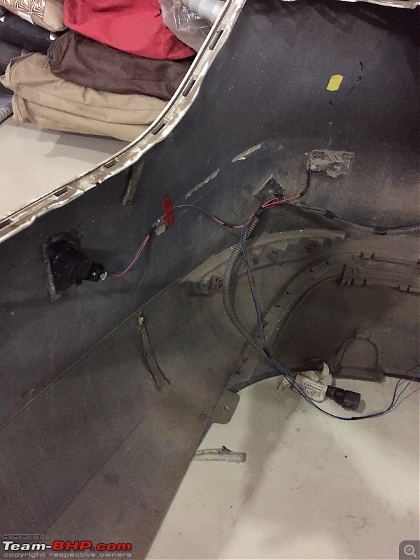
Connect
BLUE to
REAR RIGHT PLA sensor.
Connect
BLACK to
REAR LEFT PLA sensor.
Now connect blue and black wire connector with each other and this will go from trunk to PLA module, all the way through interior panels.
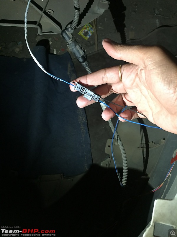
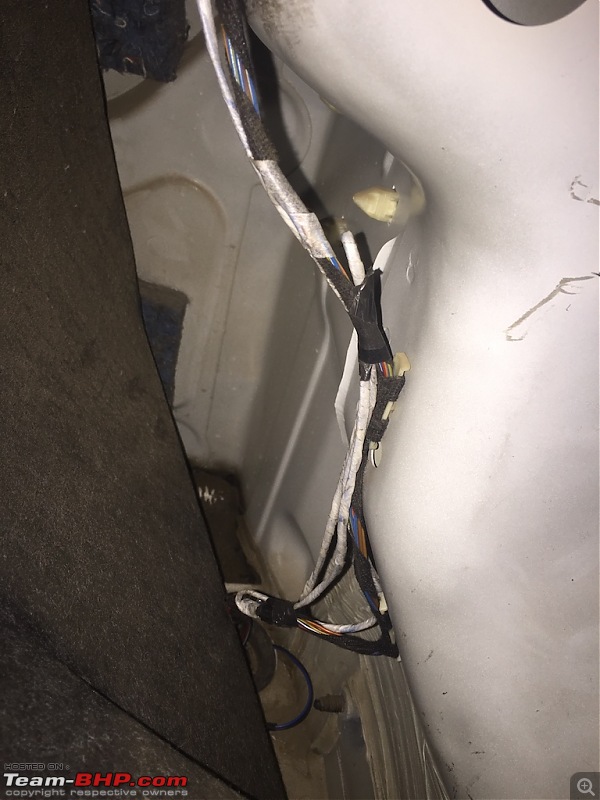
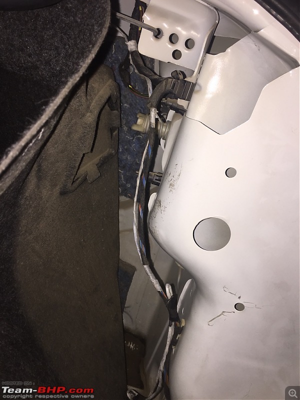
Now after all this wiring instructions, you will be wondering why I chose green wire for front and black/blue for rear.
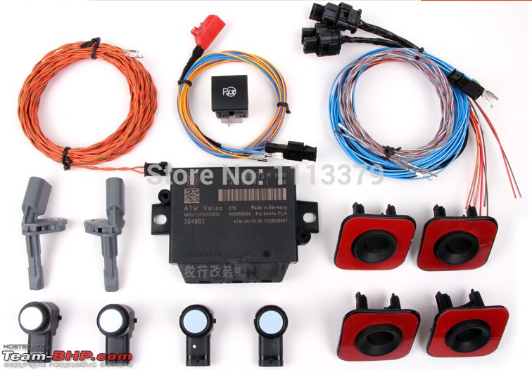
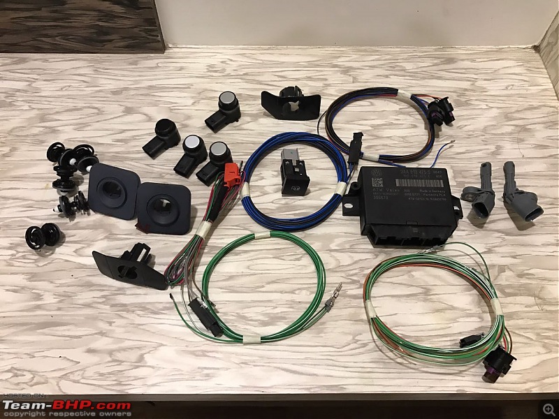
If you look closely at PLA kit, you will see that it comes with all proper connectors and proper wires. You just need to figure out which one goes where.
Green wire is short compared to blue/black so it is but obvious that blue/black will go to rear sensors.
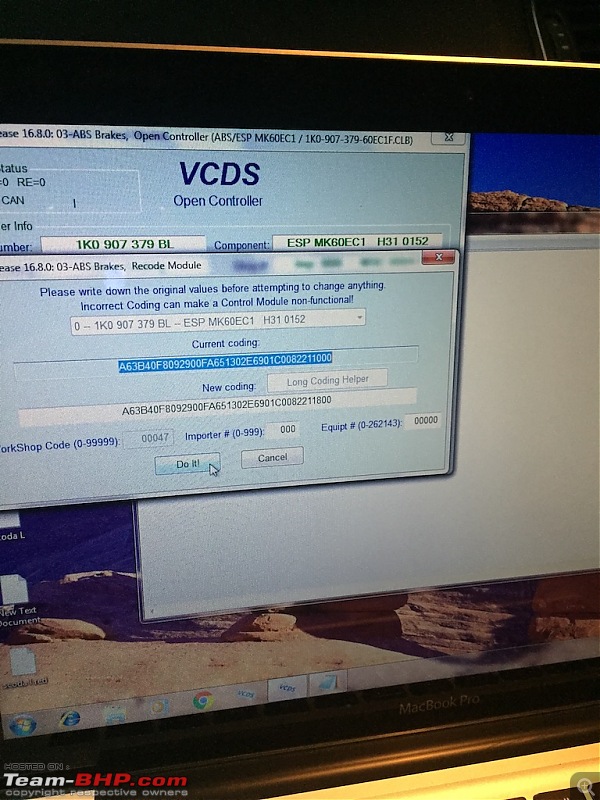
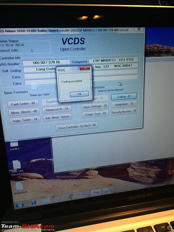
So finally done with wiring, we will head on to coding section.


 (9)
Thanks
 (9)
Thanks
 (8)
Thanks
 (8)
Thanks
 (10)
Thanks
 (22)
Thanks
 (18)
Thanks

 (16)
Thanks
 (1)
Thanks
 (1)
Thanks
 (2)
Thanks
 (1)
Thanks
 (1)
Thanks
 (1)
Thanks


