DIY #3: Installing footwell lights:
A footwell light aids in the ambient lighting in the car’s footwell regions. Some cars come with the footwell lights pre-installed whereas some do not.
Now, there are 2 ways to wire up the footwell lights in the Indian spec'd Polo from whatever homework I’ve done so far:
1. The hard way - through the BCM (Body Control Module) by stripping 2 existing wires from the 73-pin cable harness, soldering the 2 wires of the footwell light harness to cables 4 and 65 (
VW Polo 6R_BCM Connector Assignments.pdf) and enabling footwell lights through VCDS. Messing up with the stock cables will
most definitely void the warranty and VW will make an issue out of this modification later on during warranty claims if they come to know of this. Besides, light intensity of the footwell lights can only be controlled if the instrument cluster has the larger and better MFD available in the Euro-spec Polo.
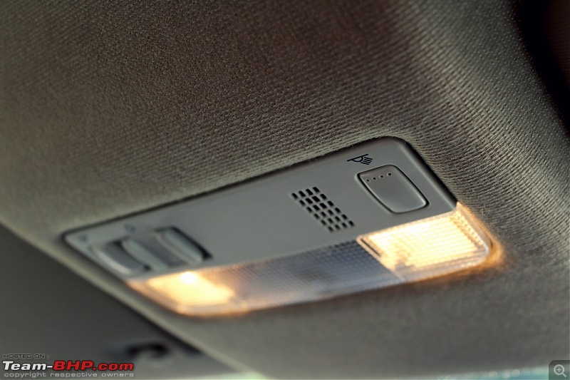
2. The easy way - by tapping a connection from the interior dome light. The dome light turns on when the car is unlocked using the key-fob and fades off when the key is turned or the car is locked. The fading or delay happens because of the dimming relay.
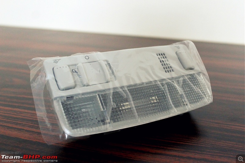
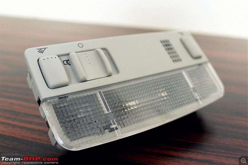
The cabin light is a perfect tapping point for the footwell lights. Since I have soldered a cable to the aftermarket dome light’s copper strips, no factory cables were spliced and taped. The entire procedure can be reversed back to the stock state and the stock dome light can be replaced in case of any issues/warranty claims in the future.
Parts Required:
1. Footwell light:

Part number -
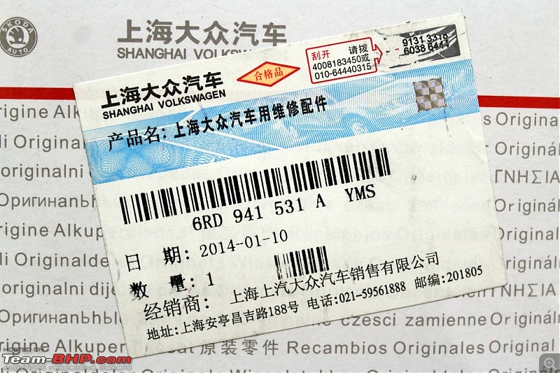
5ND 947 415. Qty - 4 nos., for lighting up each footwell.
2. Cable harness:

Qty - 1 no. The harness includes 4 connectors for the lights, a provision for the ground connector and one bare strip for the other lead.
3. 20 SWG cable:

Qty - 4 m. Available with your neighborhood electrical store. A pair of cables tapped from the dome light run through the driver side A-pillar and connects to the harness through a pair of luster terminals.
4. Luster terminal:
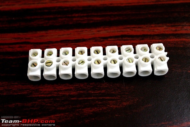
A small strip should suffice. These are also available at the local electrical shops. Took me sometime to figure out the technical name for this. Finally, Google helped me out!

5. W5W LEDs:
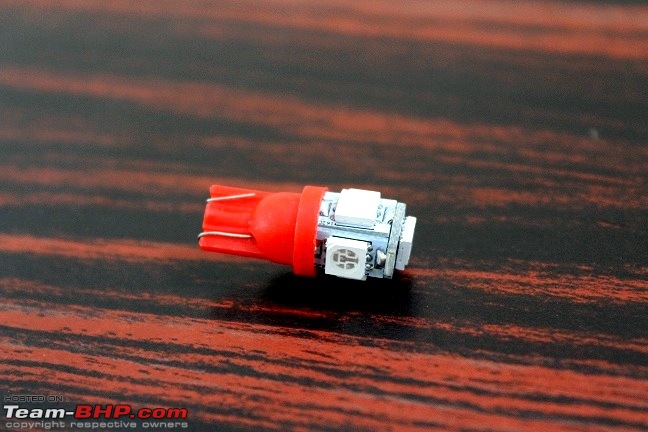
Qty - 4 nos. There are plenty of these available on eBay but please note that the cheaper imports from China are not CANBUS error free but this isn't a problem because 4 of these would consume close to 5W and the CANBUS wouldn't return any errors.
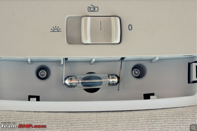
The W5W bulbs from the lamps were replaced by the LEDs (possibility of the fuse blowing up because each footwell light would consume 5W so 20W in total and the cabin light as well) and they were permanently soldered to the terminals. Soldered because the LEDs wouldn't go inside the terminals and would just pop-off.
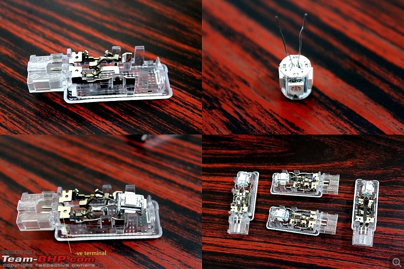
LEDs observe polarity and are usually marked as indicated in the image (top-right) above.
6. Double sided tape (3M VHB preferable).
7. Cable ties.
Tools Required:
1. Flat-tip screwdriver
2. Soldering iron
3. Solder
4. Flux
5. Prying tool
6. Hobby blade
7. Hand file
Layout:  Procedure:
1. Follow steps 1 to 3 from
DIY #1 posted above and remove the dome light.
2. Prepare the soldering iron. Using a hand file, file the bit of the iron and get rid of the old solder/dirt stuck to the tip. The tip should look bright copper in color with all the dirt removed:

Turn it on and leave it aside for 5-10 minutes.
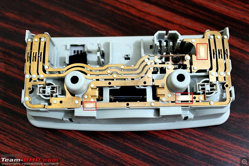
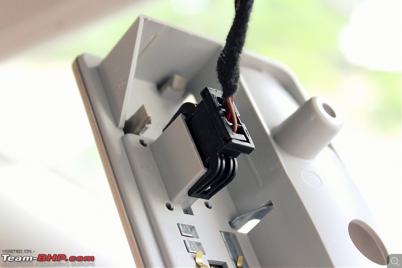
3. Using a hobby knife, scratch the copper leads of the cabin light at the locations indicated below:
4. Prepare the cables. Cut the 4 m cable into 4 parts - 2 parts of 10 cm each and 2 parts from the remaining length. Strip the ends, twist them, apply some flux and some solder on one end of the smaller cable.
5. Solder the 10 cm cables to the leads prepared in point no. 3 above and connect a luster terminal to the end.
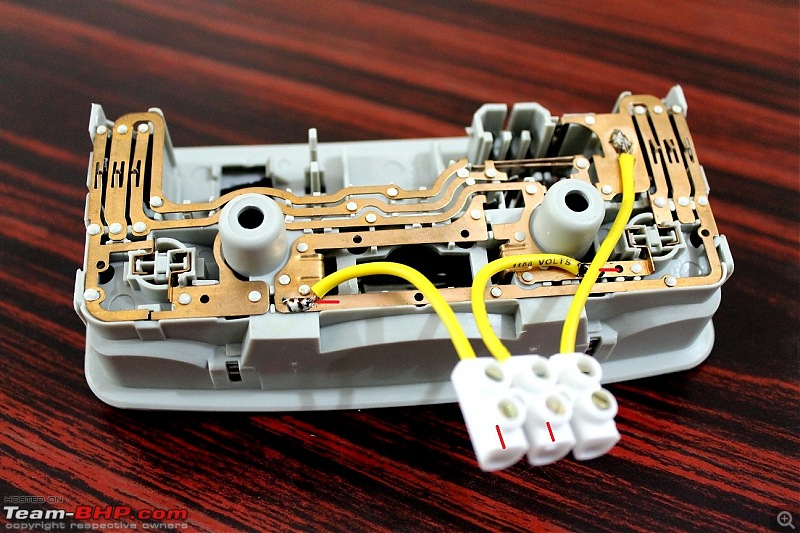
If you are wondering why I have soldered three cables here when the requirement is only two, the additional one on the top-right corner is for a later DIY which would come up shortly. The 2 yellow cables are to be connected to the terminals marked in red above.
6. Pry open the A-pillar trim and run the 2 long cables from the dome light slot through the driver-side A-pillar to the area below the steering unit.
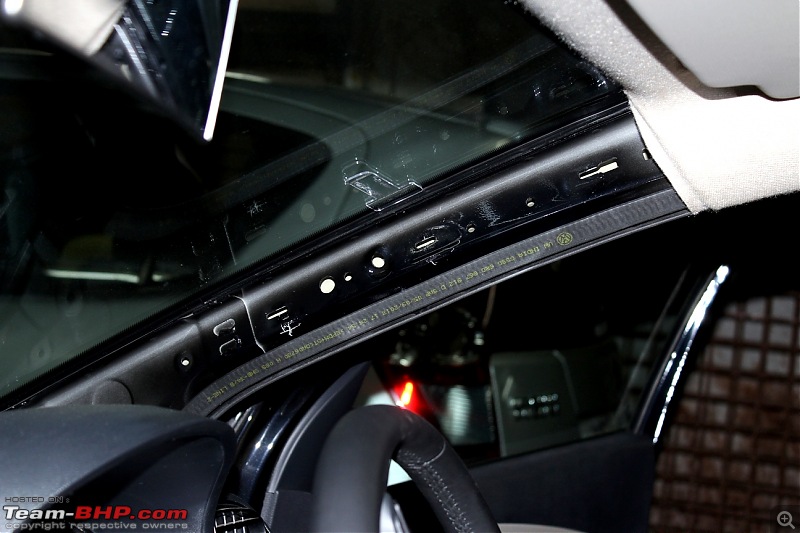
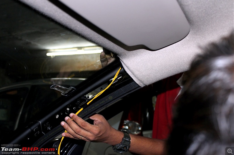
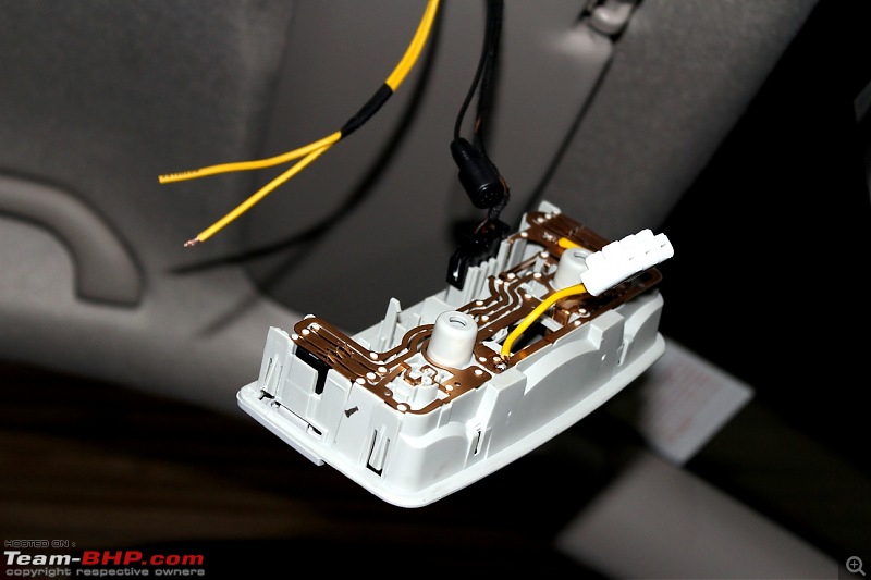
Stick the yellow cables to the A-pillar using the double-sided tape and replace the A-pillar trim:
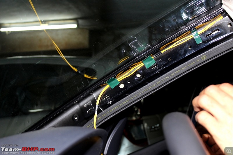
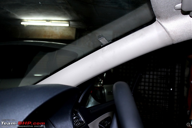
7. Pry open the flap in the dashboard towards the left of the steering unit and connect the leads of the footwell harness and the 2 nos. yellow cables to a luster terminal:


Tie the excess cables neatly using some insulation tape and tuck them in. Replace the plastic flap.
9. Route the harness towards the respective locations. To route the harness to the rear footwells, tuck them beneath the transmission tunnel flap:
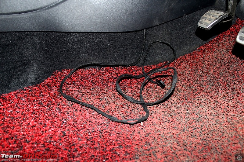

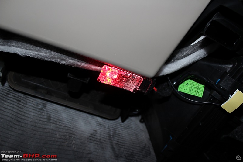
10. Connect the footwell lights to the connectors at the respective locations. The Indian spec'd Polo has only one slot for the footwell light which is for the driver side footwell:


Co-driver side footwell:
Rear footwells below the front seats:

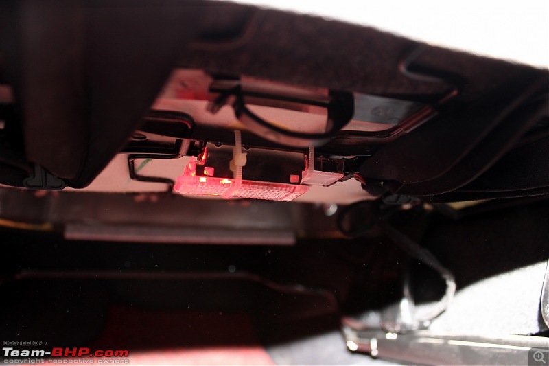

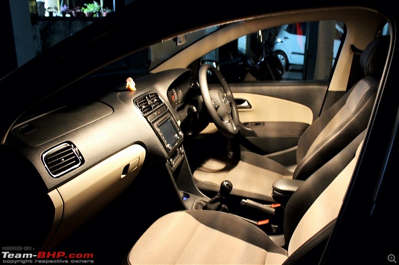
11. Test the lights using the keyfob:
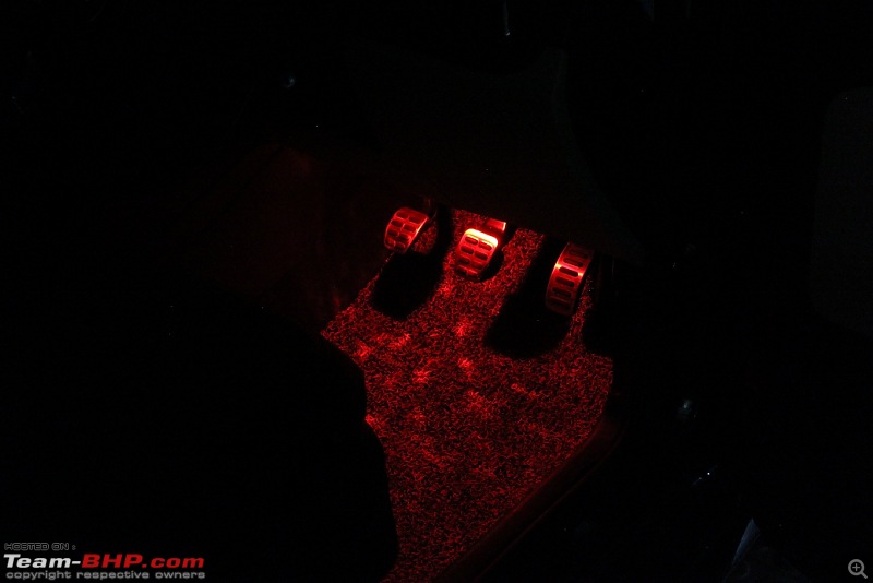


My heartfelt thanks to my roomie - Moorthy for all the help, clicking some of the snaps and helping me with routing the cables and such. You rock!

Thanks for reading!


 (38)
Thanks

 (34)
Thanks

 (62)
Thanks

 (1)
Thanks
 (1)
Thanks
 (1)
Thanks

 (8)
Thanks
 (4)
Thanks

 (2)
Thanks





















 Even though the first two here were simple DIY, I admire your patience to put out every steps, very informative and detailed, so much so it might push me to break my vow of not messing with the cars' electricals for a year! Rated a well deserved 5 star.