Installed the Delphi based RCD 510 in my car yesterday. It was a simple DIY and took 15 minutes all-in-all. I shall list down the entire procedure for this based on the 2013 cars which were shipped with the 2 CANbus connectors in the ISO connector A. Owners who wish to upgrade to this unit need to look no further - the next few posts will cover everything on this subject.

Before we begin, I wanted to point out the differences between the Delphi and the Bosch manufactured RCD 510:
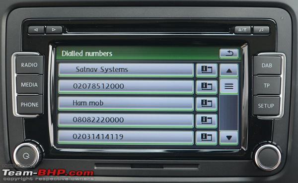
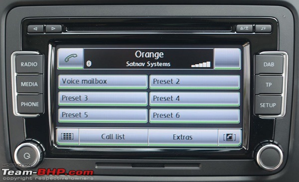
a. The Bosch unit displays the contacts’ directory and the call list whereas the Delphi unit does not. Like this:
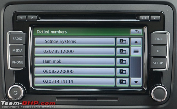
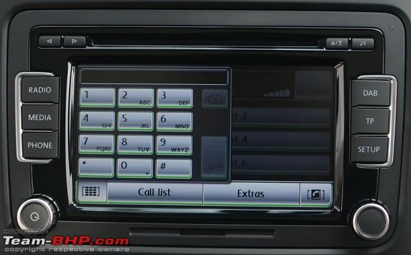
b. The Bosch unit displays the dialpad for dialing a call whereas the Delphi unit does not. Like this:

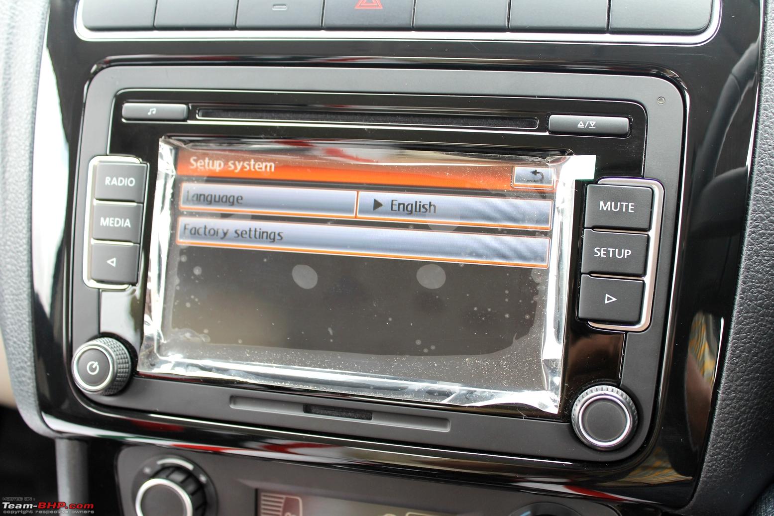
c. The Bosch unit supports multiple languages whereas the Delphi does only English and Chinese.
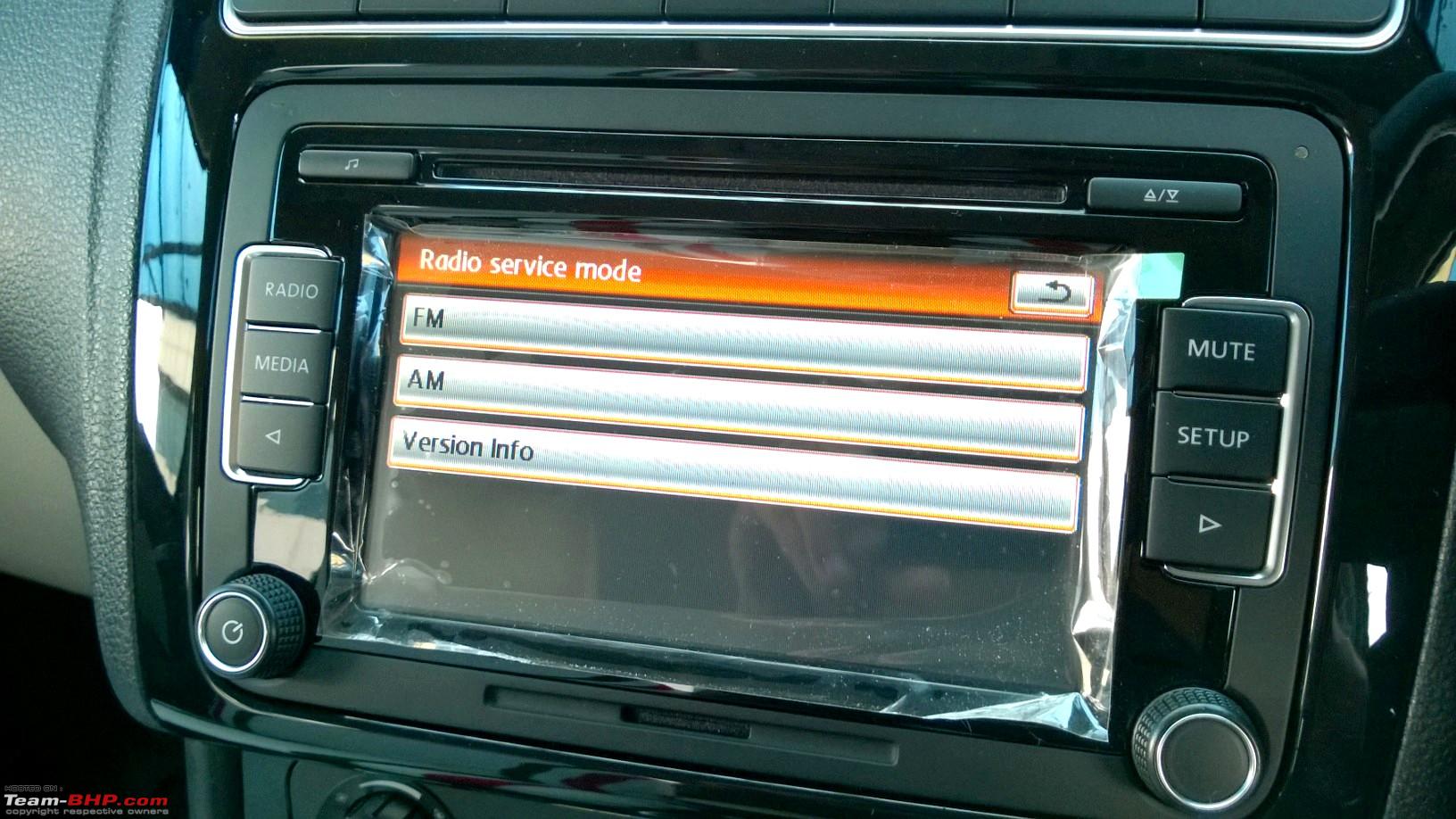
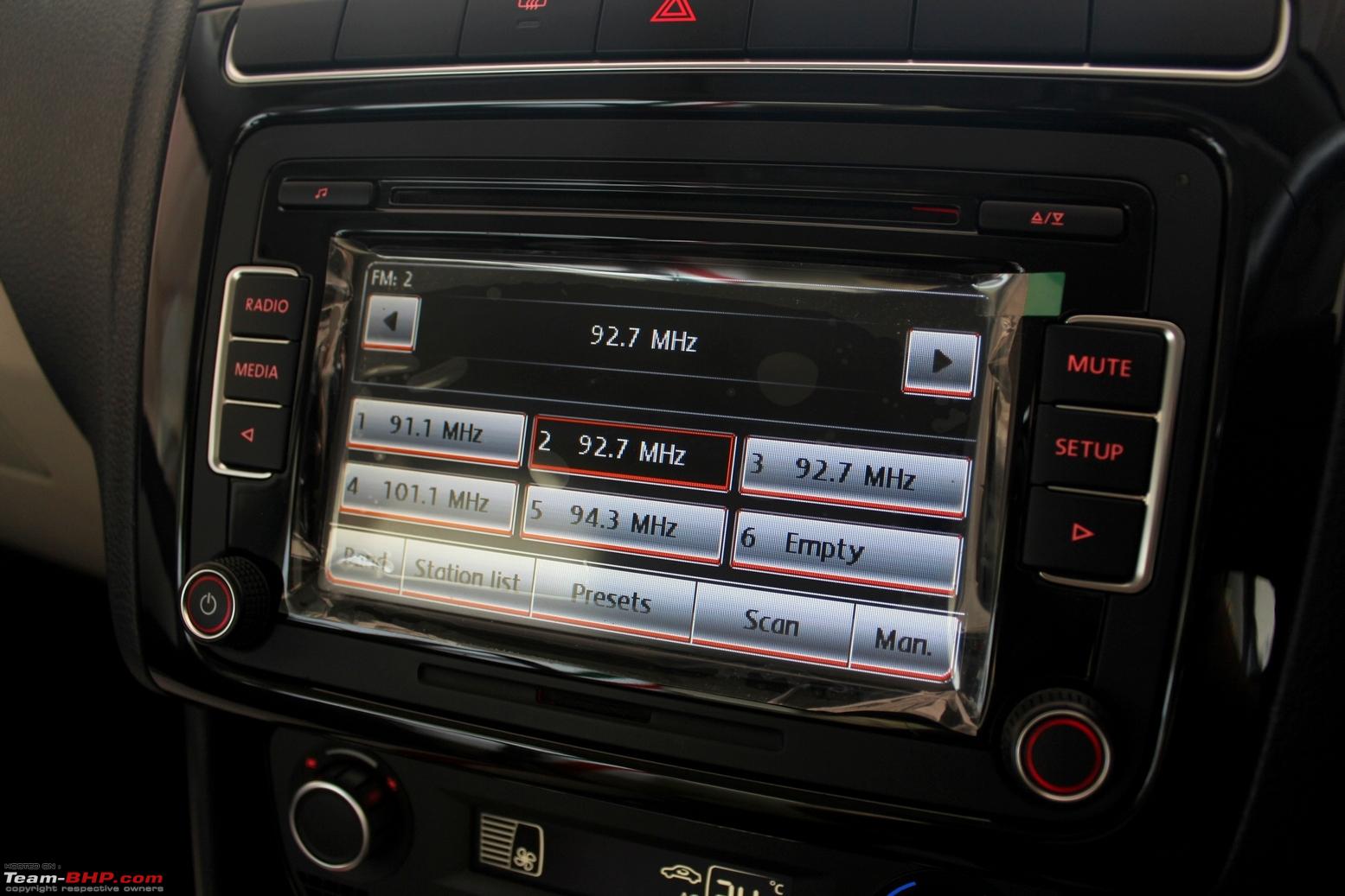
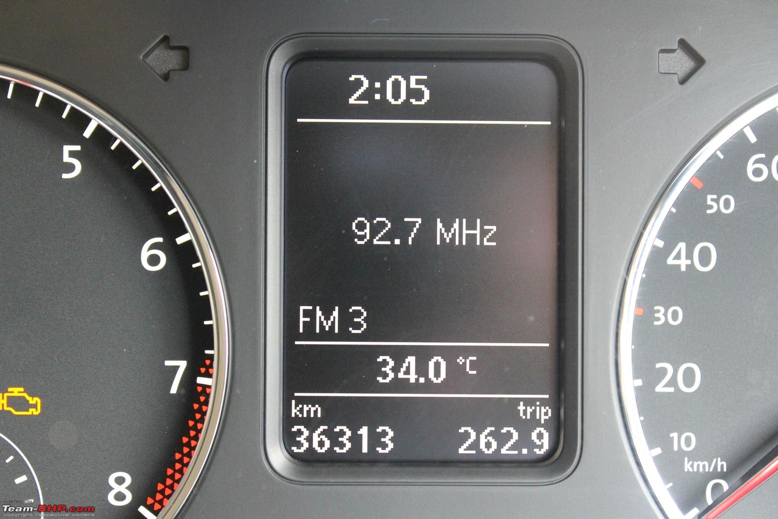
d. The Bosch unit supports digital radio (DAB) whereas the Delphi unit does only FM and AM. It doesn't matter since India does not have digital radio broadcast as yet.
e. The Bosch unit requires VW's proprietary MDI (Media Device Interface) to plug a USB mass storage device to the HU whereas the Delphi HU does it with a simple USB cable.
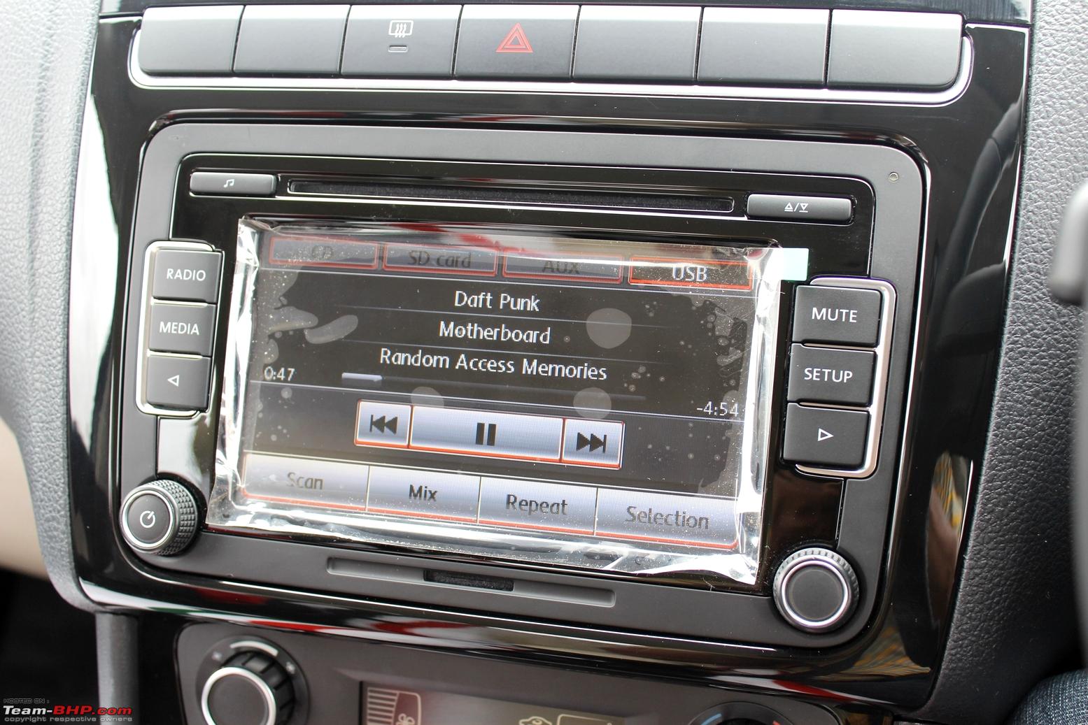
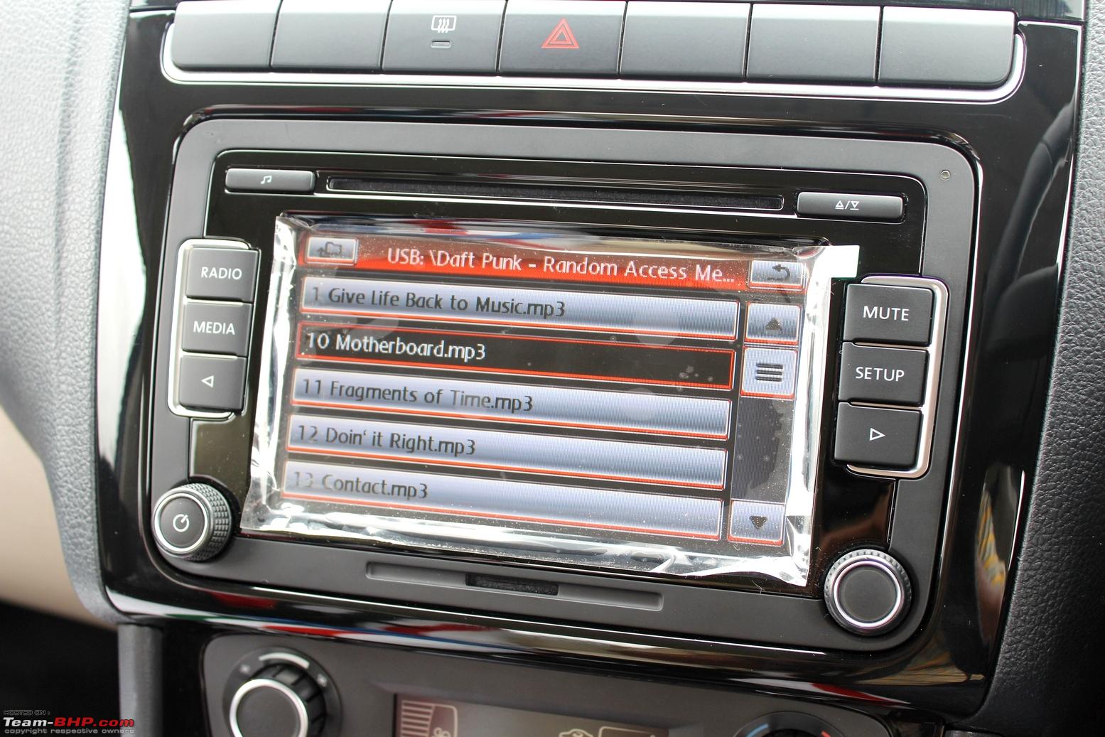
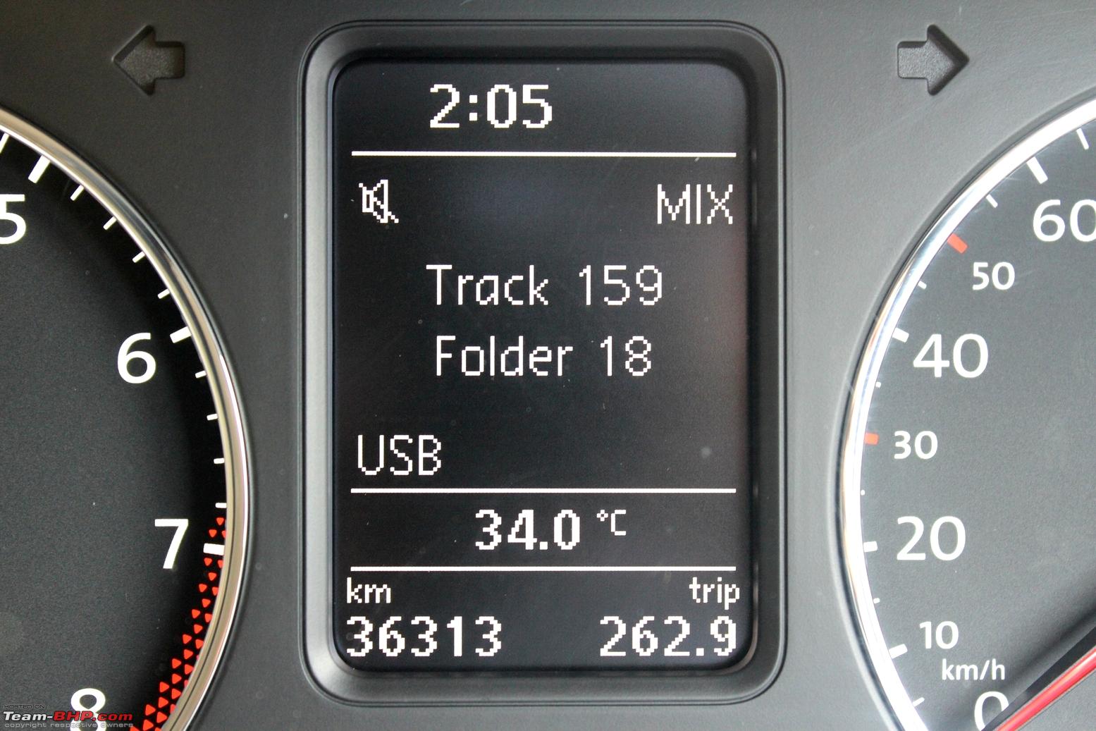
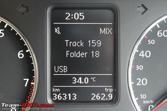
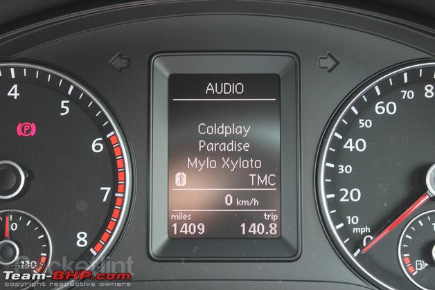
f. The Bosch unit displays the song details viz. artist, album and title on the MFD of the cluster whereas the Delphi unit only displays the track number and the folder number.
g. The Bosch unit is Made in Portugal whereas the Delphi unit is Made in China.
Parts Required:
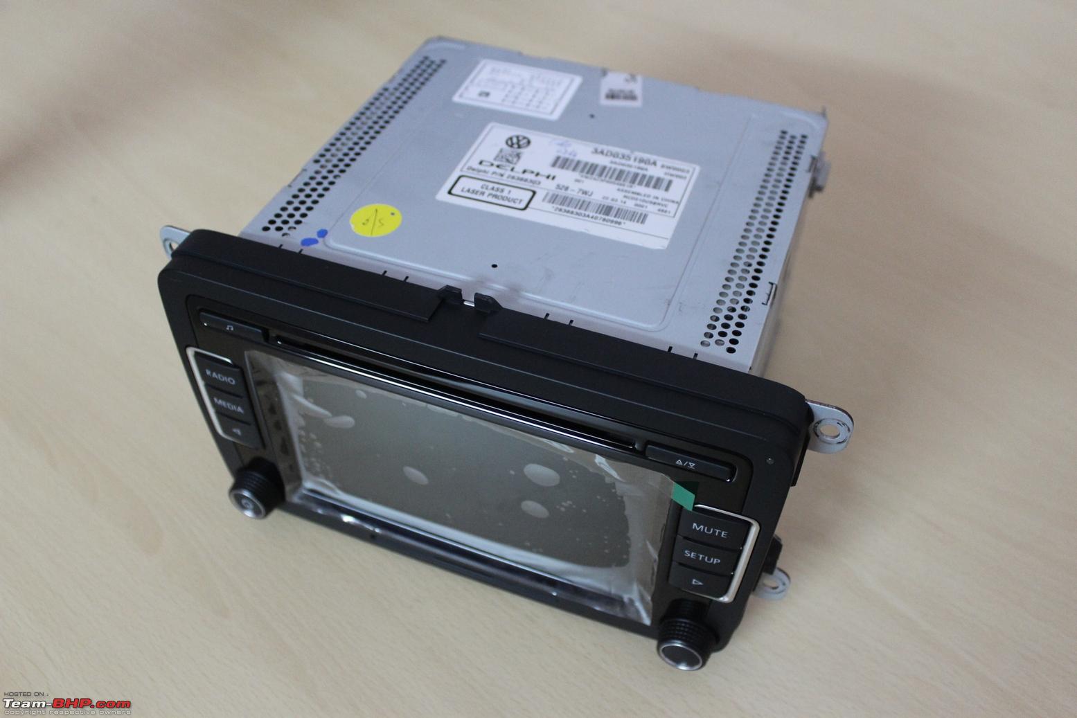
1. RCD 510 HU -
3AD 035 190A.
There are several variants of the RCD 510 unit based on the make (Delphi for the Chinese and US regions, Bosch for the EU regions) and connectors (without RVC connectivity, with RVC connectivity, with chrome knobs, with black knobs etc.). I chose the cheaper Delphi one with the RVC input. The snaps are posted below:


 Price:
 126 USD (inclusive of shipping through DHL).
Source: Aliexpress (there are various sellers - please do a site-wide search and do opt for shipping via DHL or FedEx or Aramex instead of China Post or Hong Kong Post considering this is a high value shipment). eBay.com also retails these with the seller location indicated as China.
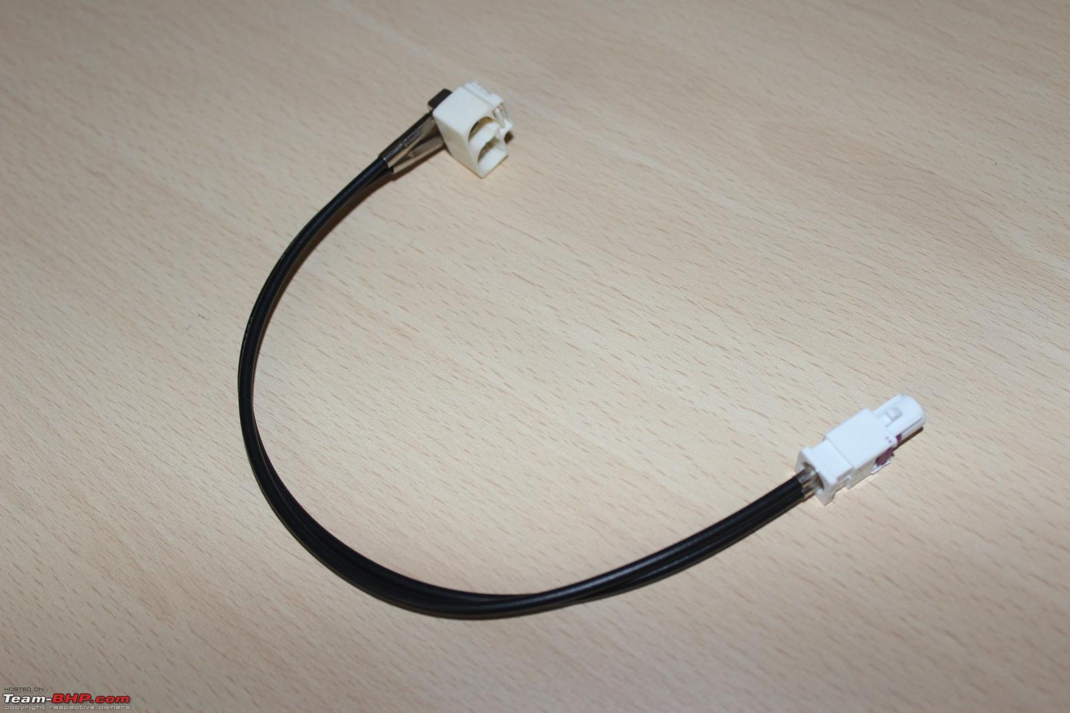
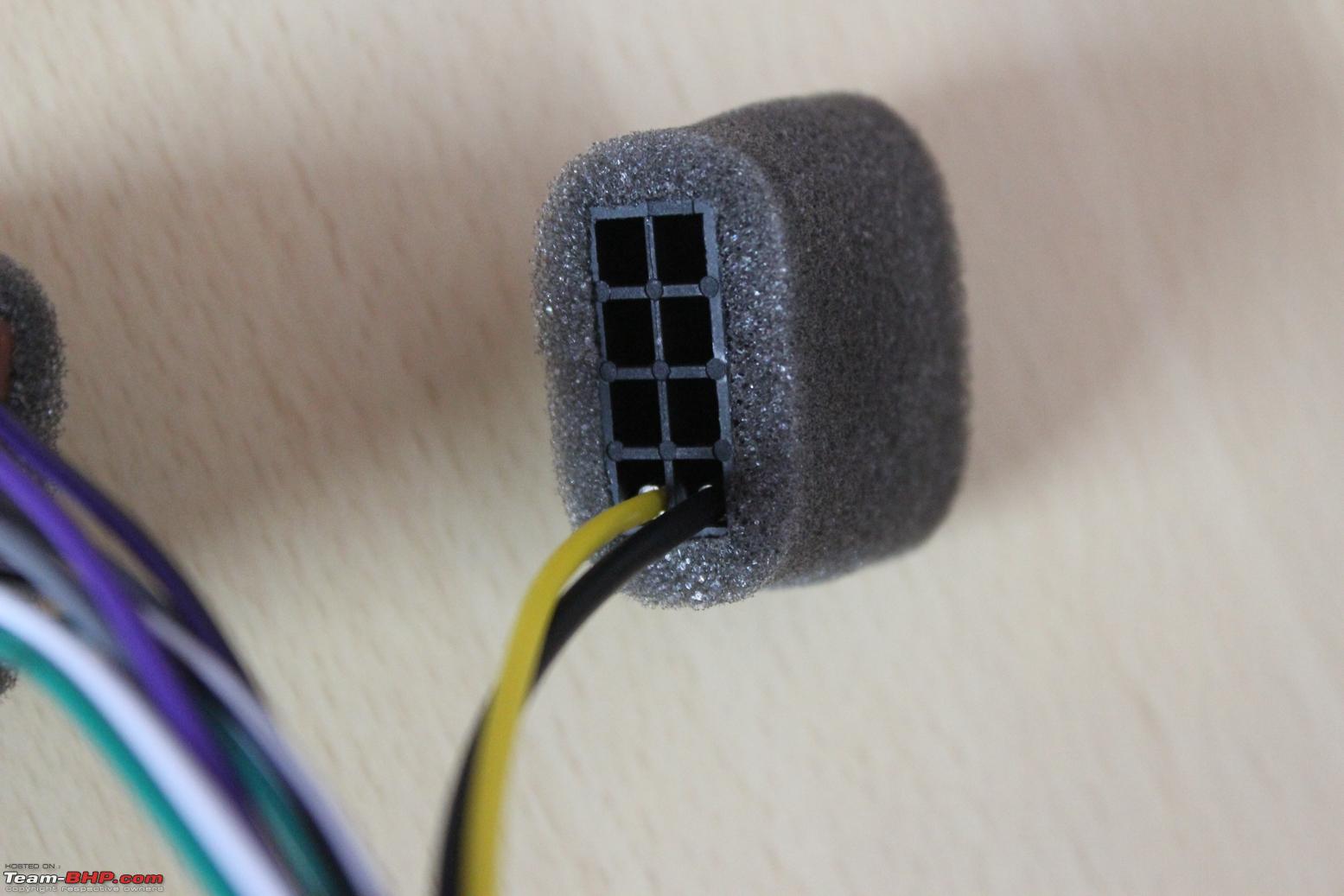
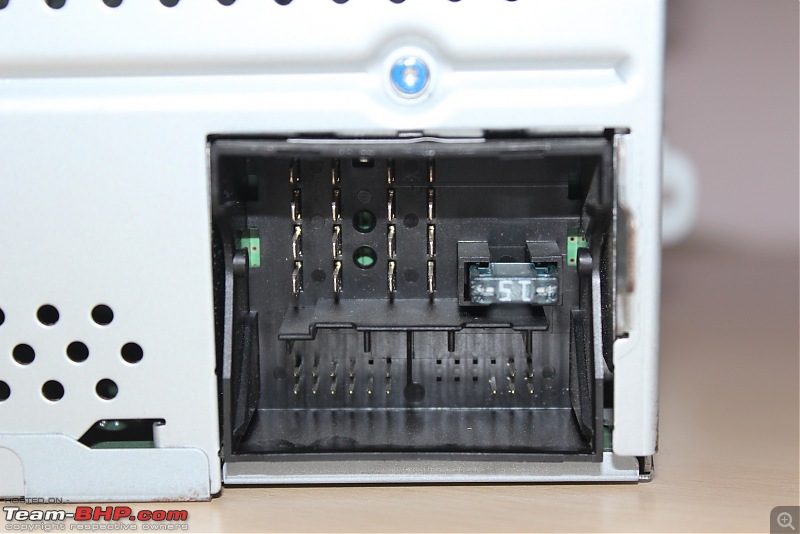
2. Radio harness adapter - 1 no.
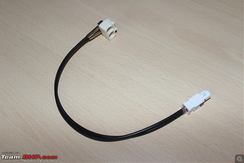


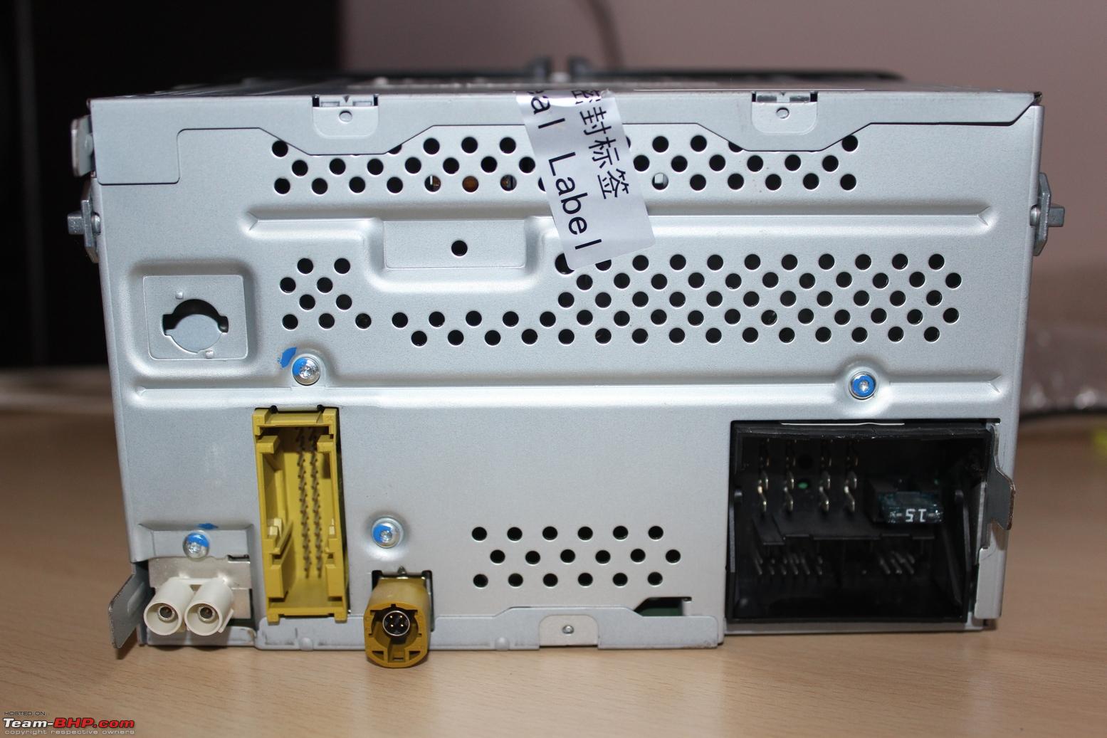
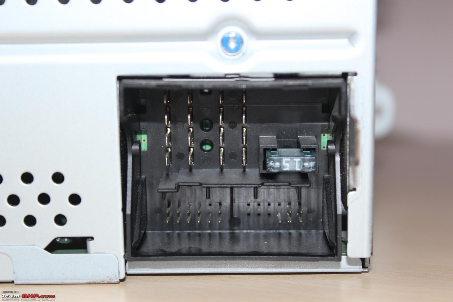
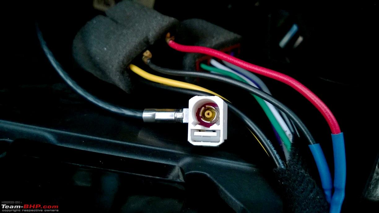
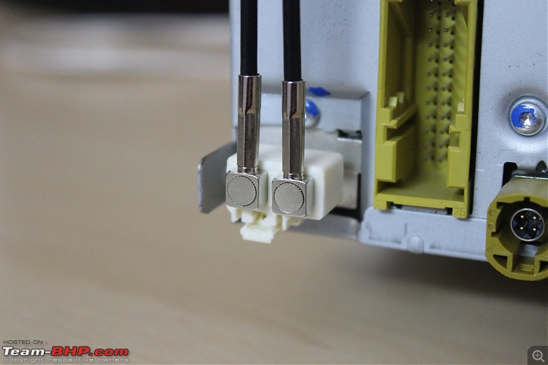
The rear of the RCD 510 has a 2 pin radio connector whereas the stock harness has a single Fakra connector:

This adapter is used to interconnect the two.
 Price:
 11 USD
Source: Aliexpress
3. USB socket + cable -
5KD 035 726A - 1 no.
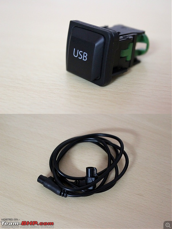
The HU does not have a USB port (!) and this accessory is required to have USB as a media source. The cable has a 90 deg. connector at one end and a straight one at the other end. They can be interchanged and connected.
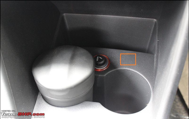
There is an alternate USB cable with a female USB socket at one end. I wanted a separate socket with the cover, since I intend to place it next to the 12V cigarette lighter socket in the plastic trim.
Price: 14 USD
Source: Aliexpress
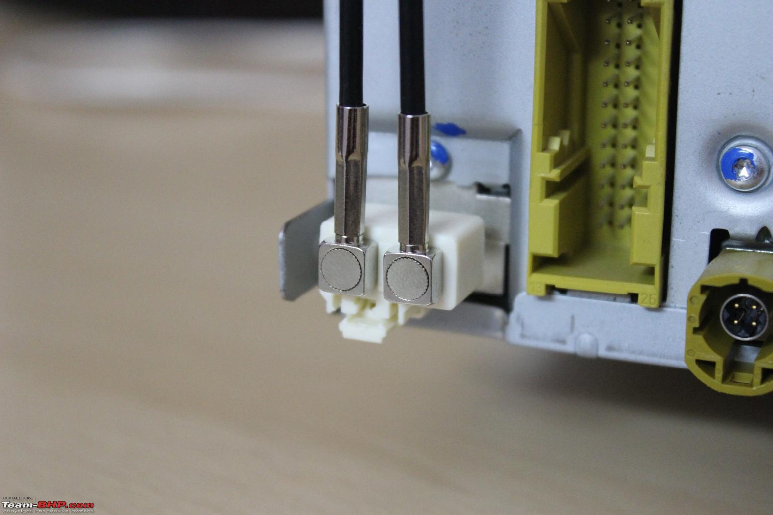
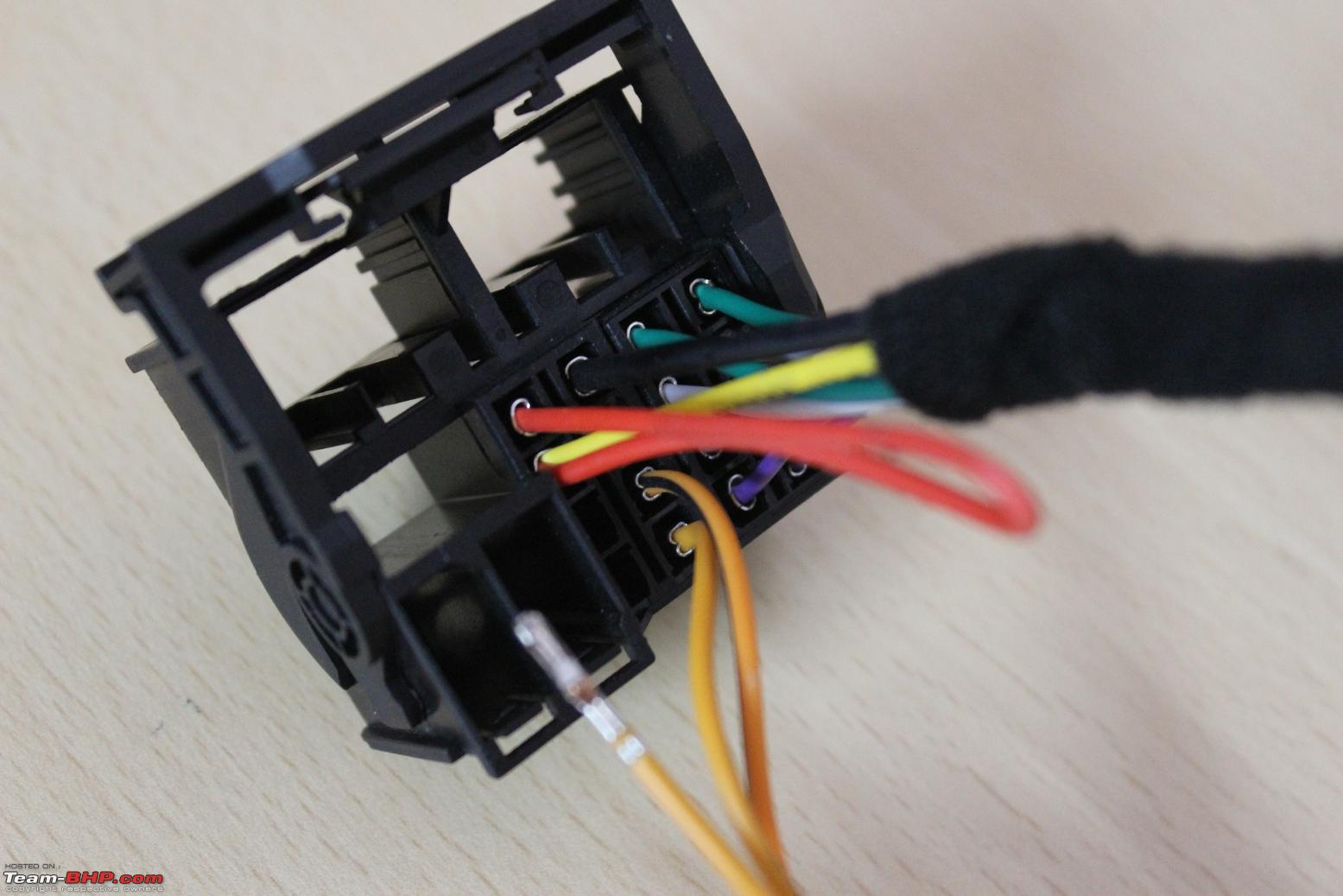
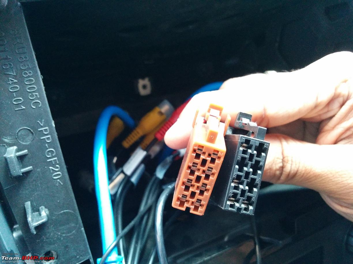
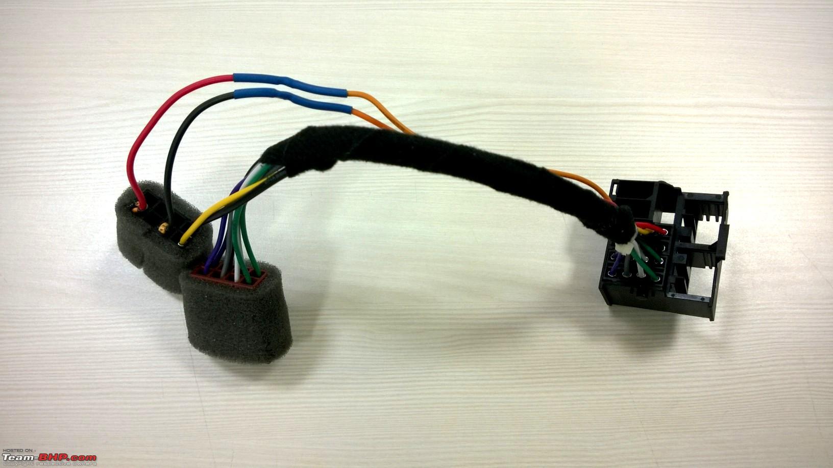
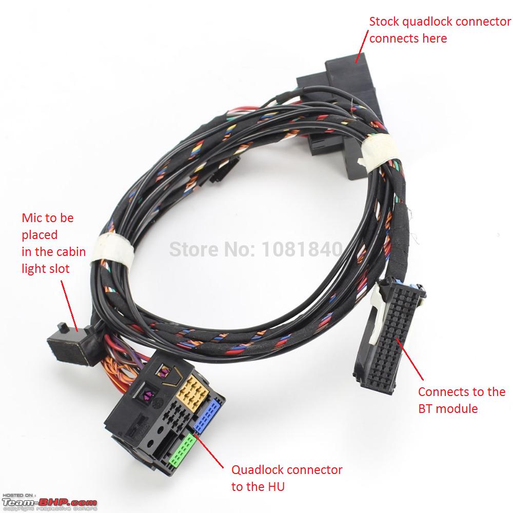
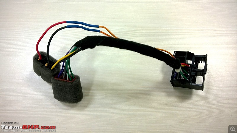
4. Quadlock to male ISO harness - 1 no.
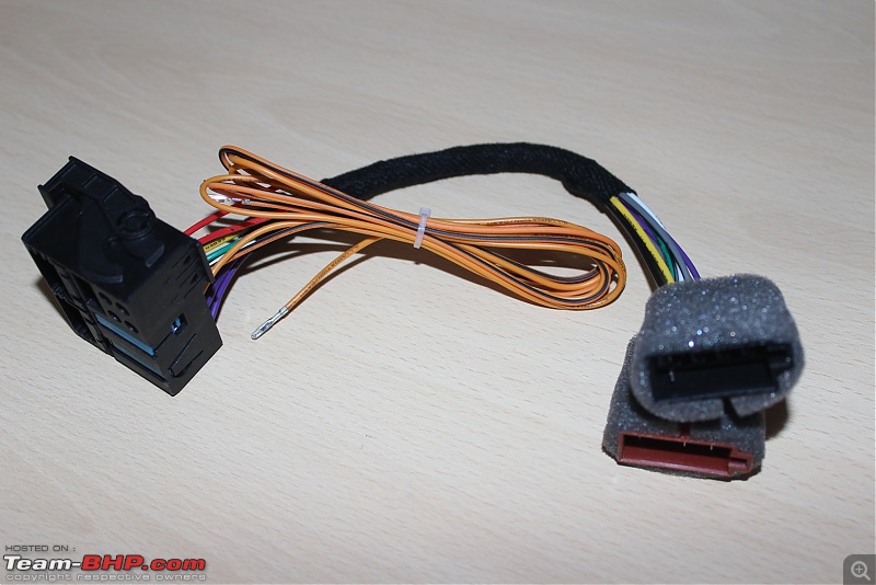
The Quadlock connector:

The male ISO connector A (CANbus + power connections):

The female ISO connector B (speaker connections):

This harness is required to connect the stock female ISO connectors to the HU’s rear. Notice the 2 bare orange colored cables with the pins zip-tied. I have explained about it in the next section.
Price: 13 USD
Source: Aliexpress
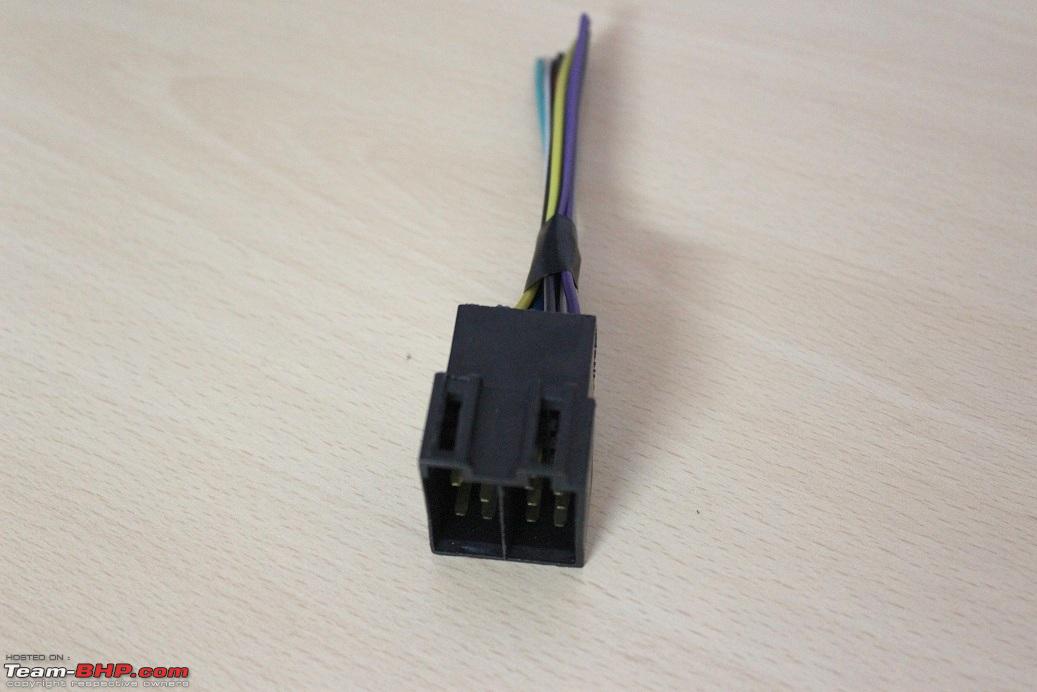
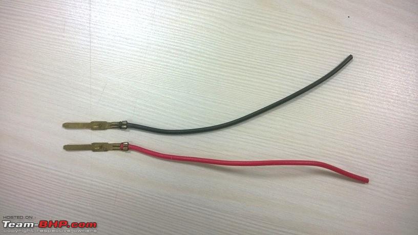
5. Spare male ISO connector with harness - 1 no.

This harness is required to salvage 2 pins along with their cables from the male connector, which are then soldered to the CANbus connector wires from the Quadlock harness. I have detailed the procedure below.
Price: Rs. 150
Source: Local car accessories outlet.
6. Heatshrink tubing - 3 mm, qty - 60 mm.
Tools Required:
1. T20 Torx screw driver.
2. Trim removing tools.
3. Heat gun.
4. Wire cutter/stripper.
5. Soldering iron.
6. Solder.
7. Flux.
8. Cable ties - 6”, 5 nos.
Pin layout
a. Stock ISO harness:
 8-pin Connector (Black) A
:
1 - CAN High (+)
2 - Not assigned
3 - Not assigned
4 - Not assigned
5 - CAN Low (-)
6 - Not assigned
7 - +12 V
8 - Ground
8-pin Connector (Brown) B:
1 - Rear right loudspeaker, positive
2 - Rear right loudspeaker, negative
3 - Front right loudspeaker, positive
4 - Front right loudspeaker, negative
5 - Front left loudspeaker, positive
6 - Front left loudspeaker, negative
7 - Rear left loudspeaker, positive
8 - Rear left loudspeaker, negative
b. RCD 510:
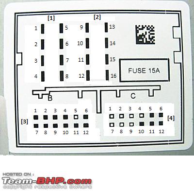 8-pin Connector [1]:
1 - Rear right loudspeaker, positive
2 - Front right loudspeaker, positive
3 - Front left loudspeaker, positive
4 - Rear left loudspeaker, positive
5 - Rear right loudspeaker, negative
6 - Front right loudspeaker, negative
7 - Front left loudspeaker, negative
8 - Rear left loudspeaker, negative
8-pin Connector [2]:
9 - CAN bus, high
10 - CAN bus, low
11 - Display voltage supply, positive
12 - Voltage supply, negative, terminal 31
13 - Display HV CAN bus low
14 - Display HV CAN bus high
15 - Voltage supply, positive, terminal 30
16 - Anti-theft coding control signal, SAFE, positive
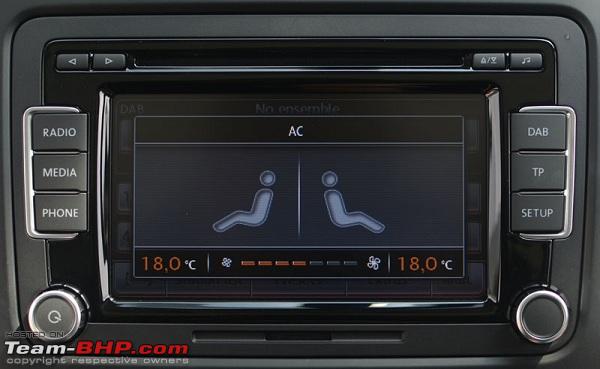
Pin nos. 11, 13 and 14 are irrelevant for the Polo and Vento. They are not connected thus. For the Jetta, pins 13 and 14 enable the climatronic display and when the HVAC settings are changed, you get this display:
 12-pin Connector [3]:
1 – AUX signal input, left
2 – AUX signal earth
3 – CD changer, audio signal earth
4 – CD changer, voltage supply, positive, terminal 30, contact continuous load greater than 1 A, temporary peak load 5 A
5 – Not assigned
6 – CD changer, DATA OUT
7 – AUX signal input, right
8 – CD changer, left audio channel, CD/L
9 – CD changer, right audio channel, CD/R
10 – CD changer, control line, switched positive
11 – CD changer, DATA IN
12 – CD changer, CLOCK (internal check protocol for data flow monitoring)
12-pin Connector [4]:
1 - Not assigned
2 - Not assigned
3 - Not assigned
4 - Not assigned
5 - Telephone audio input signal left, negative
6 - Telephone audio input signal right, negative
7 - Not assigned
8 - Not assigned
9 - Not assigned
10 - Telephone mute (mute switch for radio)
11 - Telephone audio input signal left, positive
12 - Telephone audio input signal right, positive
Quadlock to male ISO harness modification:
The Quadlock harness requires a minor modification. As indicated in the snap above, the harness comes with 2 bare cables which have to be connected to the CANbus High (+) and CANbus Low (-).
In the pre-2013 Polo and Vento cars, the ISO connectors did not come with these CANbus connectors and as a result, these cables had to be connected to the BCM’s CANbus slots or by tapping the Climatronic unit’s CANbus cables. Fortunately, the 2013 and onward cars now have the CANbus connectors in the ISO connector A.
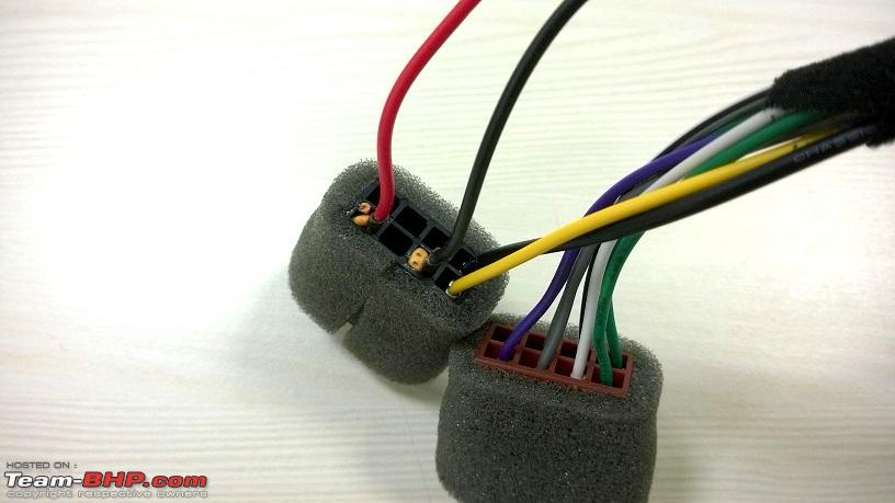
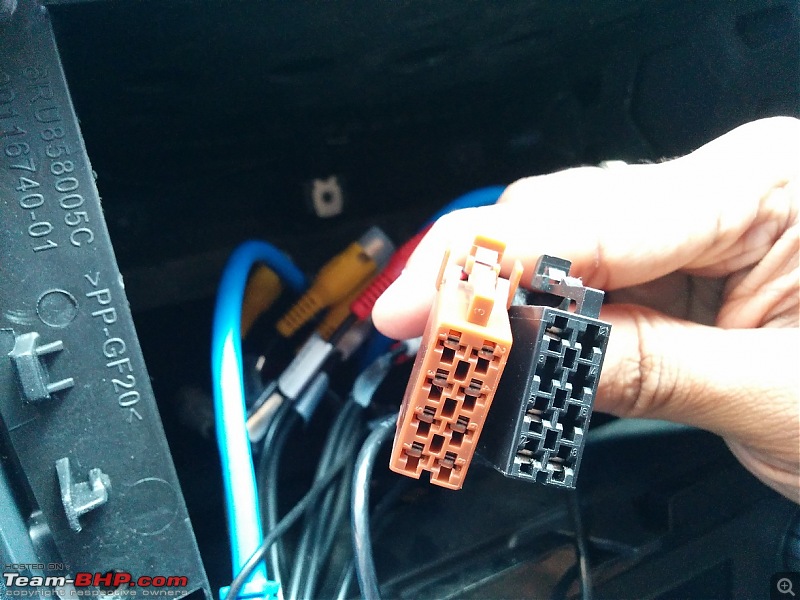
Extract 2 pins along with the wires from the spare ISO connector:


Insert the pins into the ISO connector A of the Quadlock harness, in slots 1 and 5 as shown:


In order to ensure that the pins are secured, we bent a small piece of wire in U shape, inserted it into the slot and dropped some Fevikwik glue. The pins no longer move around and was a secure fit.
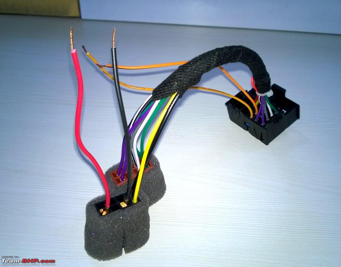
Now, the cables have to be soldered to each other. Before soldering, don't forget to slide the heatshrink tubing into both the cables. The soldering goes like this:
a. Bare wire in pin no. 9 from the Quadlock connector <> wire from pin no. 1 from the ISO connector.
b. Bare wire in pin no. 10 from the Quadlock connector <> wire from pin no. 5 from the ISO connector.
After soldering, use the heat gun to shrink the sleeves after sliding them over the soldered joints and that completes the harness modification:
Moving on to the installation of the unit.


 2nd July 2015, 17:31


 (8)
Thanks
(8)
Thanks