| Pics: Dismantling a Bicycle's Disc Brake (cable-operated)
My wife recently inherited a Mountain Bike from her "now headed to college" cousin and I had a bit of an itch of take apart and reassemble something mechanical and manageable. Since the last couple of days I have started taking apart and rebuilding each component in order to service it and learn how it works. Little background:
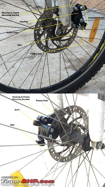
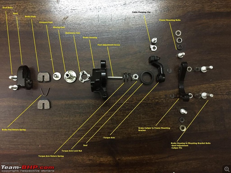
The first thing that fascinated me on bicycles were the brakes. It may be due to the fact that, I as a kid used to run out of brake pads (old rim type) every two months, doing long skids, longer than the other kids. Adjusting the brakes weekly so that they work like magic was the only thing 'bicycle maintenance, that I could understand and achieve. To me, its really gripping how knowledge of simple mechanisms enables you to make them work the way you want and in the process learn all their merits and limitations. So it goes, when bicycles started appearing with disc brakes, they were the next frontier for me to fathom. It happened after a gap of 13 years, college, employment and marriage but here it is, laid out in simple terms for everyone interested to understand. How The Disc Brake Works: 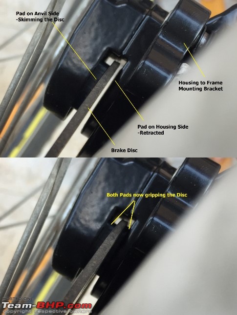 The disc is mounted on the hub and rotates with the wheel. The caliper is mounted on the fork/swing arm and is stationary in rotational terms with respect to a rotating wheel. The mounting of the caliper is in a way that the disc passes through it and in between the brake pads which are housed in the caliper. The caliper has the mechanism which when operated by a cable makes the brake pads inside the caliper move so that they sandwich the disc slowing it down and the wheel as a result slowing the bicycle down. Mounted on a bike We all know this and have seen it work marvelously in cars. But the point here is that the disc brakes in bicycles are mostly cable operated rather than being hydraulically operated. This imparts a simple mechanical dimension to these disc brakes which is quite brilliant. This is a complete breakdown of the components that make up a brake caliper.
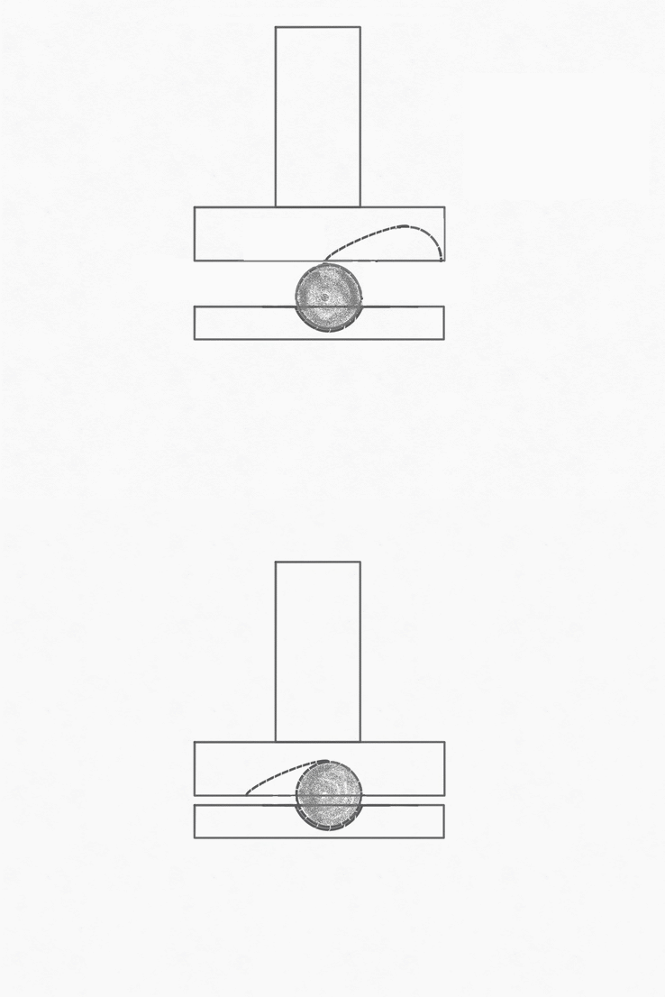
The key component at the heart of this is the ball ramp cam. This sketch shows how it transfers the rotational motion from the torque arm into linear motion of the moving brake pad. When viewed from above and anti clockwise motion of the spindle (vertical rectangle) will result in the motion shown by the GIF since the ball is held in place by the groove of the stationary cam. Cam Mechanism Please note that the actual installation of the mechanism as per assembly for the brake housing is not depicted in the GIF for simplification of the drawing. In actual assembly the spindle is passing through the stationary cam downwards.
I'll now proceed with assembly of all the components to make a working brake caliper. Install the stationary cam, Grease the ramps, place the rollers 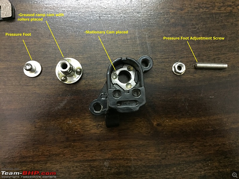 Installation of the moving cam Installation of the moving cam 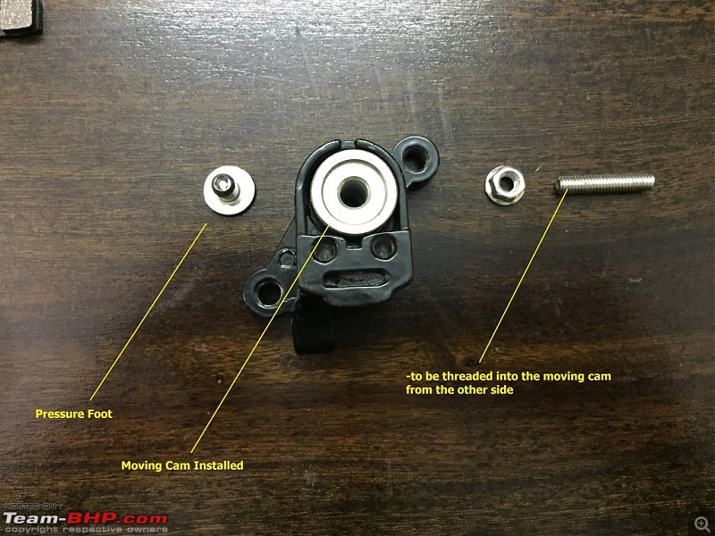 Ready for assembly Ready for assembly 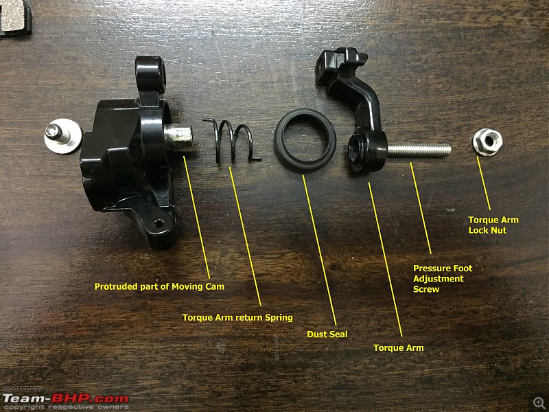 Seal, spring and foot adjustment screw installed Seal, spring and foot adjustment screw installed  Pressure foot installed and adjusted with screw Pressure foot installed and adjusted with screw  Cable clasping clip installed on lever Cable clasping clip installed on lever  Installation of anvil components Installation of anvil components 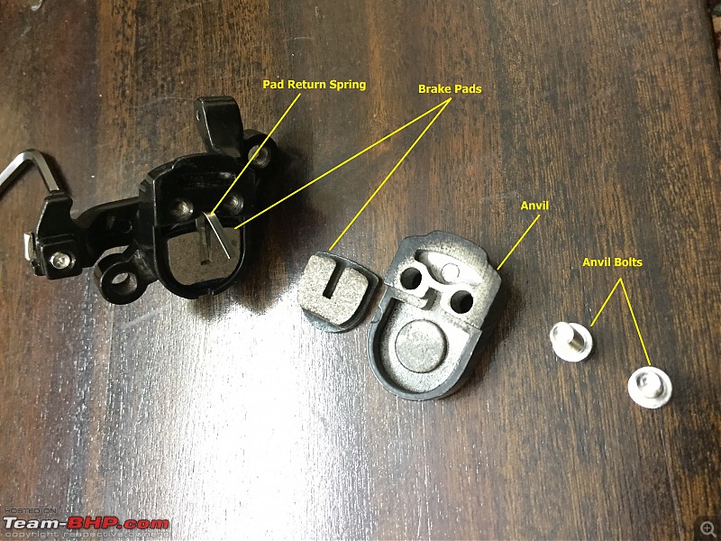 Anvil Installation in progress Anvil Installation in progress 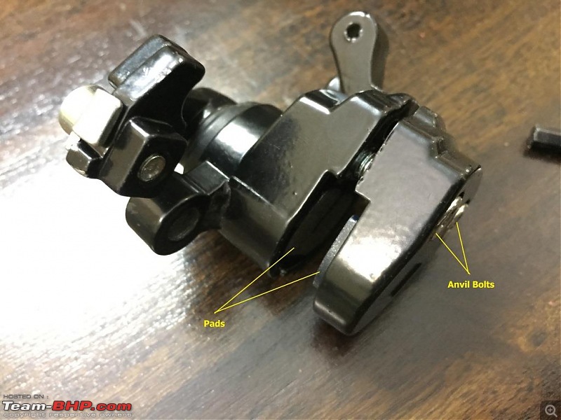 Mounting bracketry - trick part Mounting bracketry - trick part 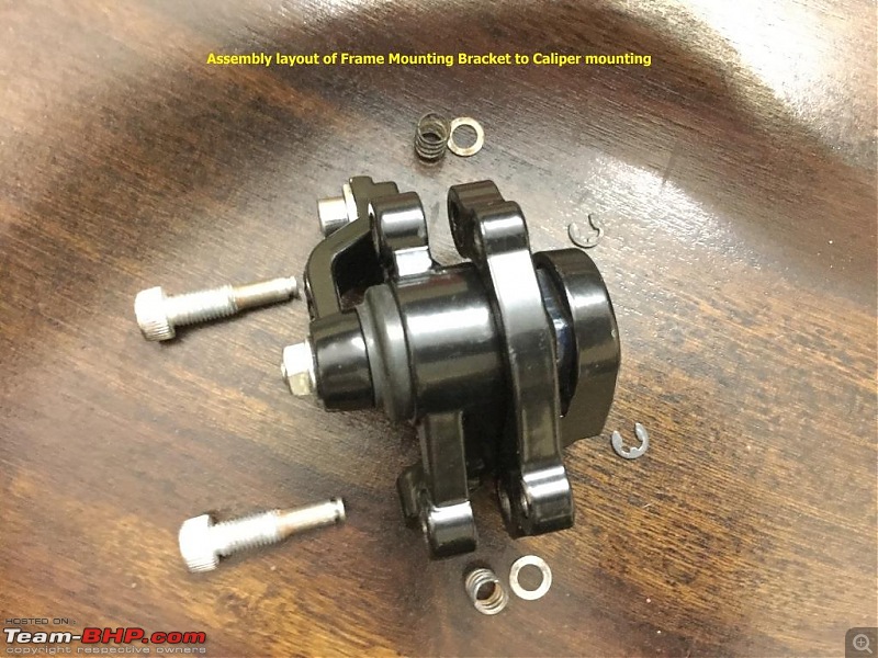 Mounting bracket installation in progress Mounting bracket installation in progress  Finished Assembly Finished Assembly 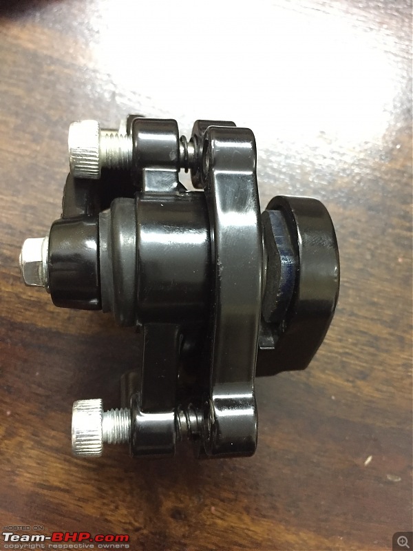 The Works - Explained The Works - Explained 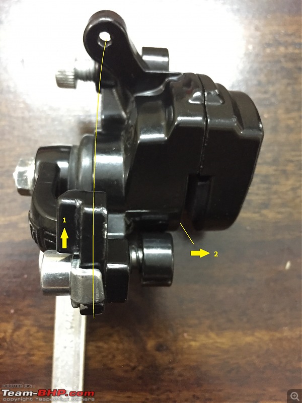 As the cable operates the torque arm in the direction depicted by Arrow-1 the rotation of the moving cam pushes the pressure foot which pushes the brake pad against the disc depicted by Arrow-2. The very slight play in the bracket mounting bolts/pins allow the caliper to move so that the stationary pad in the anvil which was earlier skimming the disc also grips the disc. A little video of the fully assembled caliper operated by hand is linked below.
Last edited by Rehaan : 16th June 2017 at 15:27.
Reason: Typo
|  (22)
Thanks
 (10)
Thanks

 (17)
Thanks
 (10)
Thanks
 (4)
Thanks
 (3)
Thanks
 (2)
Thanks
 (1)
Thanks

 (1)
Thanks
 (1)
Thanks
 (1)
Thanks







 Thanks for pointing me to this site.
